Land Rover Discovery: Rear Suspension Toe Link (G1774720) / Removal and Installation
PART(S)
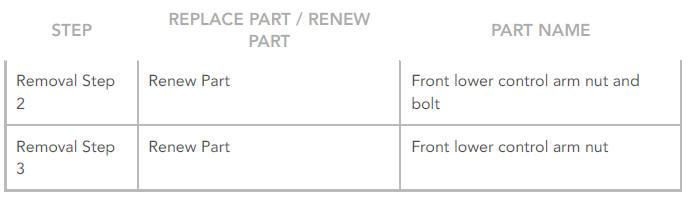
REMOVAL
NOTES:
- Some variation in the illustrations may occur, but the essential information is always correct.
- Removal steps in this procedure may contain installation details.
Refer to: Rear Subframe - AWD (502-00 Uni-Body, Subframe and Mounting System, Removal and Installation).
CAUTIONS:
- Discard the nut and bolt.
- Nuts and bolts must be tightened with vehicle at normal ride height.
Renew Part: Front lower control arm nut and bolt.
Torque:
Stage 1: 40 Nm
Stage 2: 180º
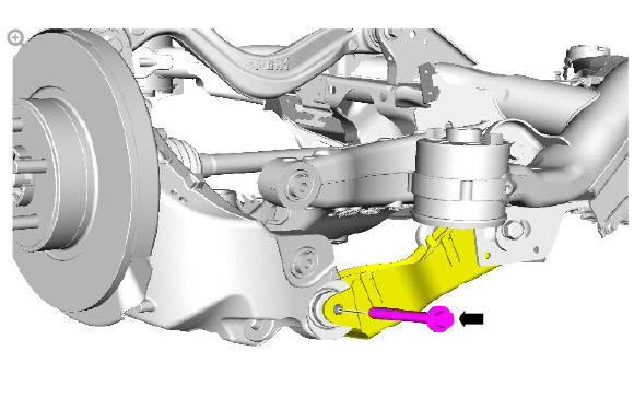
CAUTIONS:
- Discard the nut.
- Nuts and bolts must be tightened with vehicle at normal ride height.
Renew Part: Front lower control arm nut.
Torque:
Stage 1: 50 Nm
Stage 2: 60º
INSTALLATION
- To install, reverse the removal procedure.
- Using only four wheel alignment equipment approved by Land
Rover, check and adjust the wheel alignment.
Refer to: Four Wheel Alignment (204-00 Suspension System - General Information, General Procedures).
Rear suspension upper arm (G1774718) Removal and installation
REMOVAL
NOTES:
- Some variation in the illustrations may occur, but the essential information is always correct.
- Some components shown removed for clarity.
- Removal steps in this procedure may contain installation details.
WARNING:
Do not work on or under a vehicle supported only by a jack.
Always support the vehicle on safety stands.
Raise and support the vehicle.
Refer to: Rear Shock Absorber (204-02, Removal and Installation).
NOTE:
New nuts and bolts must be installed.
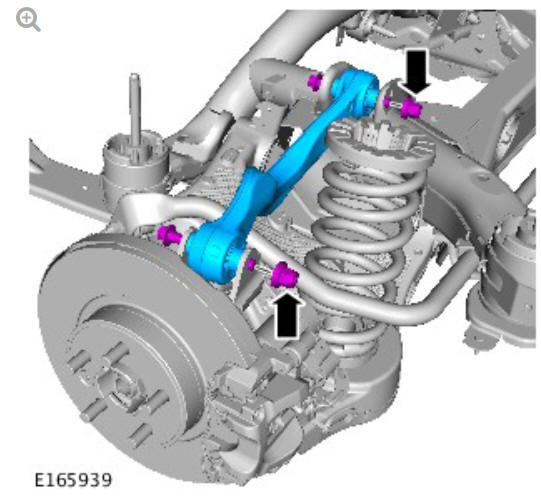
Torque:
Stage 1: 40 Nm
Stage 2: 180º
INSTALLATION
CAUTION:
Nuts and bolts must be tightened with vehicle at normal ride height.
To install, reverse the removal procedure.
Refer to: Four-Wheel Alignment (204-00, General Procedures).
READ NEXT:
 Rear Suspension Wheel
Knuckle (G1775239) / Removal
Rear Suspension Wheel
Knuckle (G1775239) / Removal
SPECIAL TOOL(S)
PART(S)
REMOVAL
CAUTIONS:
Nuts and bolts must be tightened with the weight of the vehicle on
the suspension.
Do not allow halfshafts to hang unsupported at one end or joint
dam
Rear Suspension Wheel
Knuckle (G1775239) / Installation
INSTALLATION
CAUTION:
Install a new and bolt.
NOTE:
All wheel drive transmission illustrations shown, front wheel
drive transmission is similar.
Renew Part: Wheel knuckle nut and bolt.
Torque:
Stage
SEE MORE:
Automatic transmission
The gear selection status of the rotary gear
selector and the steering wheel's gear
selector paddles (Commandshift), will be
displayed in the Message centre.
When the engine starts, the rotary gear
selector elevates from its lowered, stowed
position and the gearbox engages in Park
(P).
To selec
Fuel Charging and Controls
- Ingenium i4 2.0l Diesel
Throttle Body (G1875961)
/ Removal and Installation
REMOVAL
CAUTION:
Before disconnecting any components, make sure the area is clean
and free from foreign material. When disconnected all openings must
be sealed.
NOTE:
Some variation in the illustrations may occur, but the essential
information is always correct.
Remove the air cleaner.
Refer to: Ai
