Land Rover Discovery: Rear Suspension Wheel Knuckle (G1775239) / Removal
SPECIAL TOOL(S)
PART(S)
REMOVAL
CAUTIONS:
- Nuts and bolts must be tightened with the weight of the vehicle on the suspension.
- Do not allow halfshafts to hang unsupported at one end or joint damage will occur.
- Make sure the halfshaft constant velocity (CV) joints do not over articulate. Failure to follow this instruction may result in damage to the CV joints.
- Angularly adjusted roller (AAR) joints, used at the inboard end of some halfshafts have no internal retaining mechanism and can separate.
NOTE:
If a new knuckle is installed, a new wheel bearing must be installed.
Connect the diagnostic tool and set the electronic park brake (EPB) to the maintenance position.
WARNING:
Make sure to support the vehicle with axle stands.
Raise and support the vehicle.
Refer to: Wheel and Tire (204-04 Wheels and Tires, Removal and Installation).
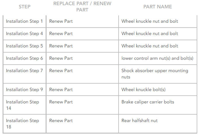
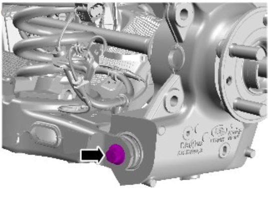
CAUTION:
Do not use air tools to remove the nut. Failure to follow this instruction may result in damage to the component.
NOTE:
Retain the nut for the instillation.
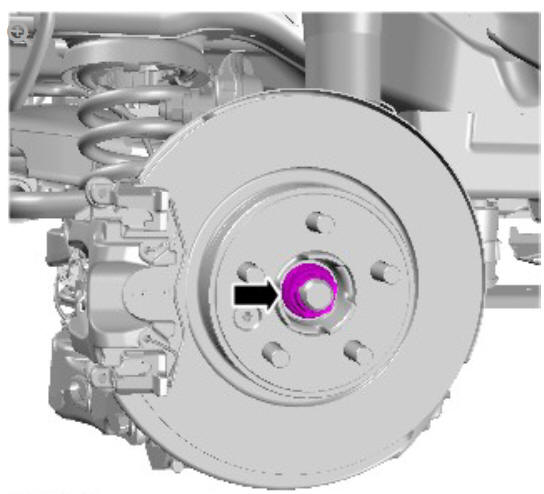
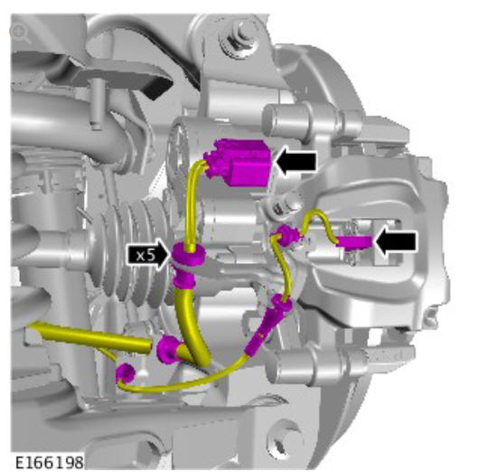
CAUTIONS:
- Discard the bolts.
- Make sure that no load is placed on the brake hose.
- Make sure that the brake hose is not twisted and is correctly located.
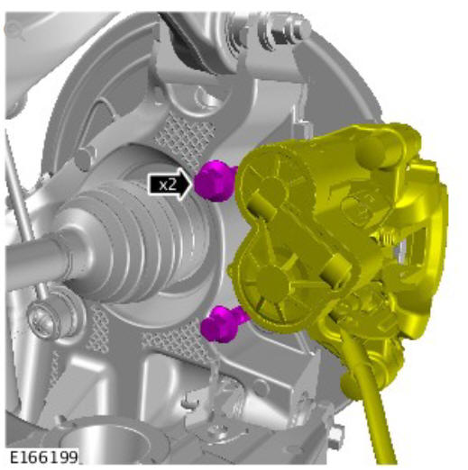
Tie aside with a suitable tie strap.
NOTE:
All wheel drive transmission illustrations shown, front wheel drive transmission is similar.
NOTE:
All wheel drive transmission illustrations shown, front wheel drive transmission is similar.
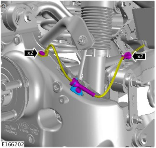
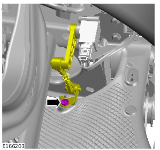
CAUTION:
Make sure the height sensor arm is pointing outwards.
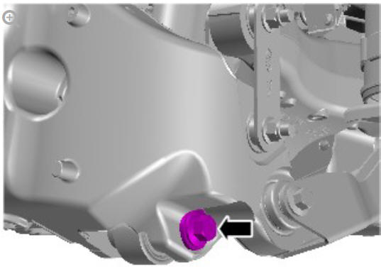
CAUTION:
Discard the bolt.
Refer to: Rear Wheel Arch Liner (501-08 Exterior Trim and Ornamentation, Removal and Installation).
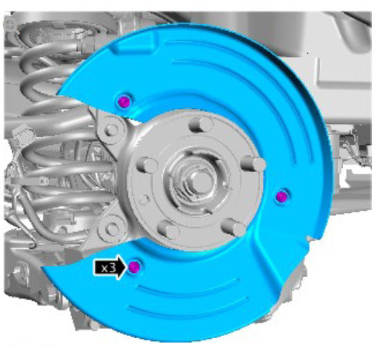
CAUTION:
Discard the nuts.
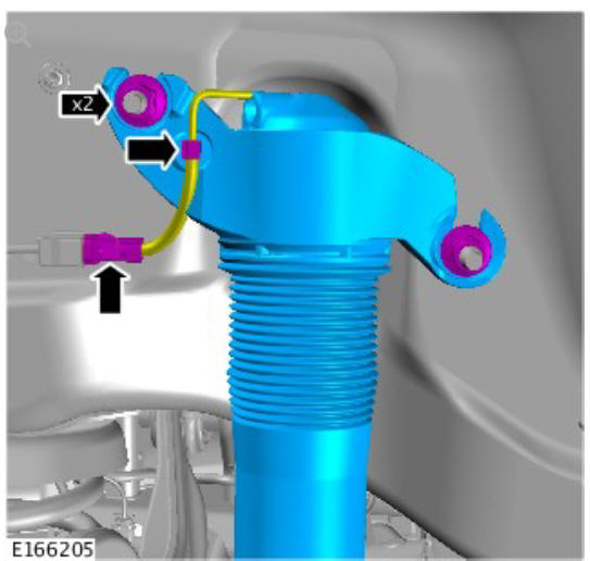
CAUTION:
Discard the nuts and bolts.
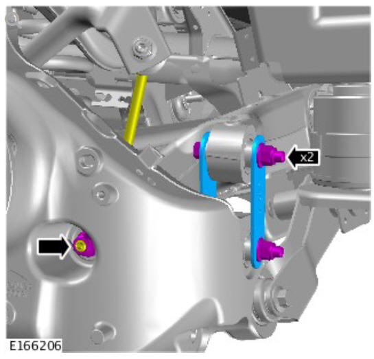
CAUTION:
Discard the nut and bolt.
NOTE:
All wheel drive transmission illustrations shown, front wheel drive transmission is similar.
CAUTION:
Discard the nut and bolt.
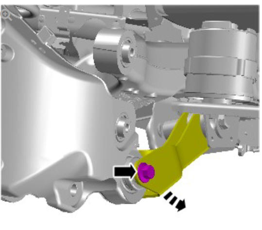
CAUTIONS:
- Make sure that the driveshaft is supported with suitable retaining straps.
- Do not use a hammer to detach the halfshaft from the hub assembly, failure to follow this instruction may result in damage to the halfshaft.
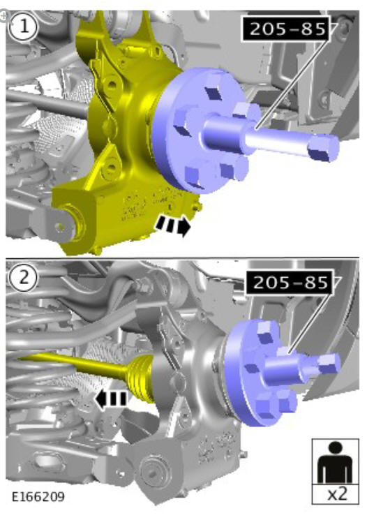
Vehicles with all wheel drive transmission (AWD).
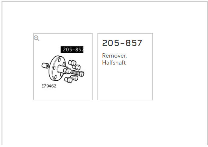
Special Tool(s): 205-857
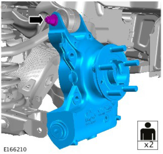
CAUTION:
Discard the nut and bolt.
NOTE:
All wheel drive transmission illustrations shown, front wheel drive transmission is similar.
READ NEXT:
 Rear Suspension Wheel
Knuckle (G1775239) / Installation
Rear Suspension Wheel
Knuckle (G1775239) / Installation
INSTALLATION
CAUTION:
Install a new and bolt.
NOTE:
All wheel drive transmission illustrations shown, front wheel
drive transmission is similar.
Renew Part: Wheel knuckle nut and bolt.
Torque:
Stage
Rear Suspension / Description and Operation
COMPONENT LOCATION
Shock absorber
Spring
Stabilizer bar
Wheel knuckle
Tie arm
Lower control arm
Subframe
Stabilizer bar link
OVERVIEW
An advanced multi-link rear suspension is introduced pr
Spring and Shock Absorber
NOTE:
Adaptive dynamics damper shown, standard damper similar.
Bolt - shock absorber to wheel knuckle
Shock absorber
Nut - Shock absorber top mounting to body fastener
Nut - shock absorber to t
SEE MORE:
Handles, Locks, Latches and
Entry Systems
- Pinpoint Tests
NOTE:
If the door is a rear door, ensure that the child locks are not engaged
and the fault is still present before continuing.
NOTE:
Ensure that the door latch claw remains in the fully latched position
during this test.
NOTE:
Ensure that the door latch claw remains in the fully latch
Four-Wheel Drive
Systems - Vehicles
With- Active
Driveline Transfer
Case Draining and
Filling (G1964387)
General Procedures
DRAINING
WARNING:
Make sure to support the vehicle with axle stands.
CAUTION:
Make sure the vehicle is on a flat level surface.
Raise and support the vehicle.
Remove the engine undershield.
Refer to: Engine Undershield (501-02 Front End Body Panels,
Removal and Installation).
CAUTION:
Make sure tha
