Land Rover Discovery: Rear Suspension Spring (G1774680) / Removal and Installation
GENERAL EQUIPMENT
.jpg)
REMOVAL
CAUTION:
Do not remove the rubber isolators form the spring. A new spring is installed with the correct isolators.
NOTES:
- Some variation in the illustrations may occur, but the essential information is always correct.
- Some components shown removed for clarity.
- Removal steps in this procedure may contain installation details.
WARNING:
Do not work on or under a vehicle supported only by a jack.
Always support the vehicle on safety stands.
Raise and support the vehicle.
Refer to: Wheel and Tire (204-04, Removal and Installation).
.jpg)
.jpg)
General Equipment: Transmission jack
WARNING:
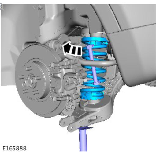
Use two suspension spring compressors located on opposite sides of the spring. Make sure the suspension spring compressors are correctly installed. Refer to manufactures instructions.
.jpg)
General Equipment: Suspension Spring Compressor
NOTE:
Make sure that a new bolt is installed.
.jpg)
Torque: 170 Nm
NOTE:
Make sure that a new nut and bolt are installed.
.jpg)
Torque:
Stage 1: 40 Nm
Stage 2: 180º
NOTE:
Make sure that a new nut and bolt are installed.
.jpg)
Torque:
Stage 1: 40 Nm
Stage 2: 60º
NOTE:
Make sure that a new bolt is installed.
.jpg)
Torque:
Stage 1: 40 Nm
Stage 2: 180º
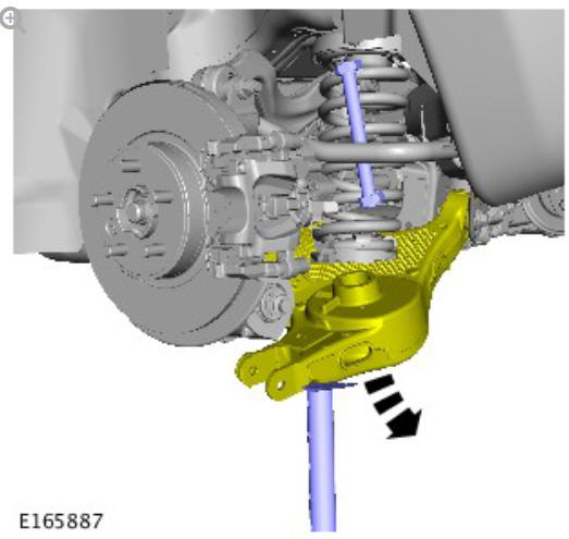
General Equipment: Transmission jack
INSTALLATION
CAUTIONS:
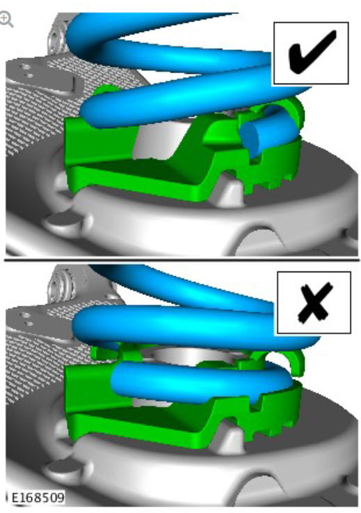
- Make sure to install the spring and isolator in the correct position.
- Nuts and bolts must be tightened with vehicle at normal ride height.
To install, reverse the removal procedure.
Refer to: Specifications (204-00, Specifications).
READ NEXT:
 Rear Suspension Toe
Link (G1774720) / Removal and
Installation
Rear Suspension Toe
Link (G1774720) / Removal and
Installation
PART(S)
REMOVAL
NOTES:
Some variation in the illustrations may occur, but the essential
information is always correct.
Removal steps in this procedure may contain installation details.
Refer to:
Rear Suspension Wheel
Knuckle (G1775239) / Removal
SPECIAL TOOL(S)
PART(S)
REMOVAL
CAUTIONS:
Nuts and bolts must be tightened with the weight of the vehicle on
the suspension.
Do not allow halfshafts to hang unsupported at one end or joint
dam
SEE MORE:
Engine Mount (G1913572) / Removal and Installation
PART(S)
REMOVAL
WARNING:
Make sure to support the vehicle with axle stands.
Raise and support the vehicle.
Refer to: Cooling System Draining, Filling and Bleeding (303-03B
Engine Cooling - INGENIUM I4 2.0L Diesel, General Procedures).
Refer to: Accessory Drive Belt (303-05B Accessory Drive - INGENI
Telephone system overview
For information on connecting a
Bluetooth phone or device.
Note: Some Telephone system features
will not operate unless the SD card
supplied with the vehicle is inserted
correctly into the SD card slot.
Change device: Touch to search for a
new, or change to another paired
phone or device.
Mes
