Land Rover Discovery: Variable Geometry Turbocharger (VGT) Vane Actuator
The VGT vane actuator is located on the side of the turbocharger.
The actuator comprises a 12V DC motor which operates a worm drive to move the actuator arm to adjust the vane position.
The ECM controls the output to the vane actuator motor using a Pulse width modulation (PWM) output.
The motor also contains an angular position sensor. The ECM outputs a 5V reference voltage to the position sensor and the sensor returns a ground and a signal proportional to the actuator position.
ELECTRIC THERMOSTAT
The electric thermostat is located below the intake manifold.
The electric thermostat can operate in two ways; the wax in the thermostat is heated up by both the engine coolant and an electric heating element within the thermostat. The electric thermostat allows the ECM to regulate the engine temperature according to load requirement. The operation of the electric heater element is controlled by the ECM using various parameters from other engine sensors and a stored operating map.
The electric thermostat receives a battery voltage from the Engine Junction Box (EJB). The ECM controls the thermostat operation by using a controlled ground.
GLOW PLUG CONTROL MODULE
.jpg)
The glow plug control module is located in the right side of the engine compartment.
There are three phases of glow plug heating: Pre heating, crank heating and post heating. The ECM determines the power levels for each phase and heating times from the coolant temperature.
When the stop/start switch is operated to start the engine, the ECM calculates any required heating times and, if heating is required, sends a Local Interconnect Network (LIN) bus signal to the glow plug control module. The glow plug control module energizes the glow plugs with the required power levels. If required by the ECM, the glow plug control module keeps the glow plugs energized during cranking and for the duration of any post heating phase.
The glow plug control module monitors the drive circuit of the glow plugs for plausibility of operation, continuity, and short and open circuits. If a fault is detected, the glow plug control module sends a signal to the ECM, which then stores a related fault code.
ACCELERATOR PEDAL POSITION (APP) SENSOR
Accelerator pedal demand is communicated to the ECM by two potentiometers located in the APP sensor. The ECM uses the two signals to determine the position, rate of movement and direction of movement of the pedal.
The ECM supplies a 5V reference voltage and a ground for each potentiometer.
ENGINE COOLING FAN CONTROL MODULE

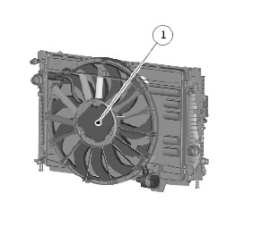
- Engine cooling fan control module
The ECM determines when to operate the cooling fan from the Engine Coolant Temperature (ECT) sensors input and/or a cooling fan request from the Automatic Temperature Control Module (ATCM). The ECM also adjusts the fan speed to compensate for the ram effect of vehicle speed.
The ECM varies the duty cycle of the PWM signal to the cooling fan control module between 0 and 100% to operate the fan motor in one of four modes: Off, minimum speed (750 RPM), linear variable speed between minimum and maximum speeds, and maximum speed (2820 RPM). Under hot operating conditions, the fan may continue to operate for up to five minutes after the engine has been switched off.
The cooling fan control module monitors for over and under input voltage, a stalled motor and a partially stalled motor. If it detects any of these faults the cooling fan control module temporarily pulls the PWM signal to ground to notify the fault to the ECM. The length of time the PWM signal is pulled to ground varies between 2 and 8 seconds, depending on the fault. The cooling fan control module repeats the notification process at 5 second intervals until the fault is cleared. If there is more than one fault, only the highest priority fault is notified to the ECM. Fault priorities, in descending order, are over voltage, under voltage, stalled motor and partially stalled motor. The ECM records a related DTC for faults notified by the fan control module and signals the IC on the HS-CAN powertrain systems bus to display a warning message.

