Land Rover Discovery: Manual Transmission - Transaxle External Controls Gearshift Lever (G1781378) / Removal and Installation
Land Rover Discovery (2009–2016) Service Manual / Powertrain / Manual Transmission Transaxle
and Clutch / Manual Transmission - Transaxle
External Controls
Gearshift Lever (G1781378)
/ Removal and Installation
REMOVAL
NOTES:
- Removal steps in this procedure may contain installation details.
- Some variation in the illustrations may occur, but the essential information is always correct.
NOTE:
Neutral must be selected before the cables are released to allow the cables to be correctly set on the install.
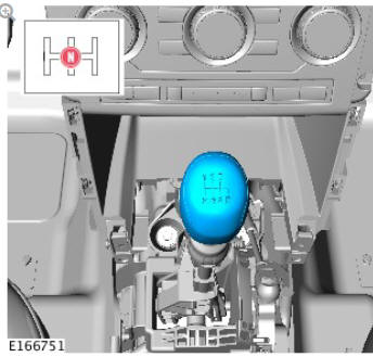
Refer to: Floor Console (501-12 Instrument Panel and Console, Removal and Installation).
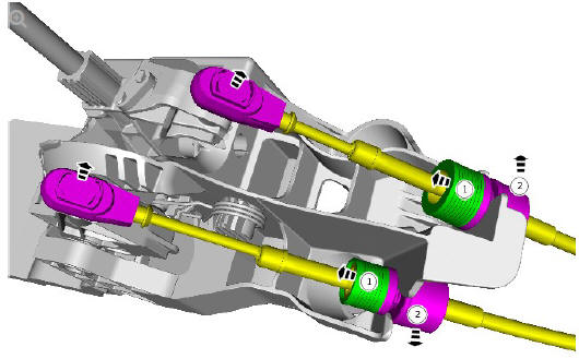
- Release the locking ring.
- Release the gear selector cable.
.jpg)
INSTALLATION
- To install, reverse the removal procedure.
- Refer to: Gearshift Cable Adjustment (308-00 Manual Transmission/Transaxle and Clutch - General Information, General Procedures).
Manual Transmission - Transaxle External Controls Gearshift Lever Knob (G1781379) / Removal and Installation
REMOVAL
NOTES:
- Removal steps in this procedure may contain installation details.
- Some variation in the illustrations may occur, but the essential information is always correct.
WARNING:
The selector knob will be released suddenly, keep face clear during removal.
.jpg)
CAUTIONS:
- Carefully release either side of the component to avoid damage.
- Do not disassemble further if the component is removed for access only.
.jpg)
INSTALLATION
- To install, reverse the removal procedure.
READ NEXT:
 Manual Transmission - Transaxle
External Controls
Gearshift Linkage (G1781377)
/ Removal and Installation
Manual Transmission - Transaxle
External Controls
Gearshift Linkage (G1781377)
/ Removal and Installation
REMOVAL
NOTES:
Removal steps in this procedure may contain installation details.
Some variation in the illustrations may occur, but the essential
information is always correct.
CAUTION:
Make sure
Manual Transmission - Transaxle
External Controls
/ Description and Operation
COMPONENT LOCATION
Selector lever knob
Selector lever
Selector lever housing
Selector lever cables
OVERVIEW
The manual transmission external controls comprise a selector lever
assembly and two
SEE MORE:
Front Suspension Front
Shock Absorber (G1779642) - Installation
Installation
Make sure the correct vehicle suspension components are installed.
Refer to: Specifications (204-00 Suspension System - General
Information, Specifications).
Inspect the component and install a new one if damaged.
Inspect the component and install a new one if damaged.
Insp
Front end Sheet Metal
Repairs Front
Side Member and
Suspension Top
Mount
Assembly (G1770869) - Removal
Removal
NOTE:
The front side member and suspension top mount assembly is
installed in conjunction with:
Front bumper cover
Front bumper
Front bumper mounting
Hood
Hood latch panel
Radiator
Condenser
Front fender
Fender splash shield
Fender apron panel
Fender apron panel reinforcement
En
© 2019-2025 Copyright www.lrdisc.com
