Land Rover Discovery: Front Disc Brake Brake Caliper Anchor Plate (G1785106) / Removal and Installation
Land Rover Discovery (2009–2016) Service Manual / Chassis / Chassis-Brake-System / Front Disc Brake Brake Caliper Anchor Plate (G1785106) / Removal and
Installation
PART(S)
REMOVAL
NOTE:
Removal steps in this procedure may contain installation details.
WARNING:
Make sure to support the vehicle with axle stands.
Raise and support the vehicle
Refer to: Wheel and Tire (204-04 Wheels and Tires, Removal and Installation).
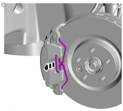
CAUTION:
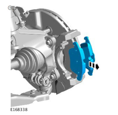
Do not allow the brake caliper to hang on the brake hose.
Tie aside.
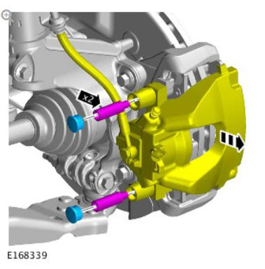
CAUTIONS:
- Discard the bolts.
- This step only applies to vehicles up to VIN H995605 using the M14 fixing.
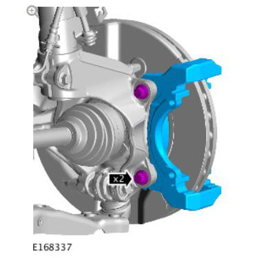
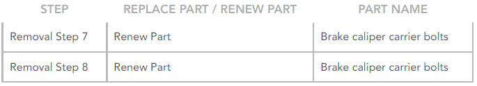
Renew Part: Brake caliper carrier bolts.
Torque: 200 Nm
CAUTIONS:
- Discard the bolts.
- This step only applies to vehicles from VIN H995606 using the M12 fixing.
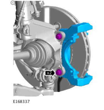
Renew Part: Brake caliper carrier bolts.
Torque:
Stage 1: 90 Nm
Stage 2: 120º
INSTALLATION
CAUTION:
Install new brake caliper anchor plate retaining bolts.
To install, reverse the removal procedure.
READ NEXT:
 Front Disc Brake Brake Disc (G1785104) / Removal and Installation
PART(S)
REMOVAL
WARNING:
If installing a new brake disc, install new brake pads.
CAUTION:
Brake discs must be renewed in pairs.
NOTE:
Left hand illustration shown, Right hand is similar.
WARNING:
Ma
Front Disc Brake Brake Pads (G1785103) / Removal and Installation
REMOVAL
WARNING:
Brake pads must be renewed in axle sets only. Failure to follow this
instruction may result in braking efficiency being impaired.
NOTES:
Left illustration shown, right is similar.
General Information Brake System Bleeding (G1785100) / General Procedures
NOTES:
Bleeding of the complete brake system must be carried out using
Land Rover approved diagnostic equipment. Where only the
primary or secondary brake circuits have been disturbed in
isolatio
SEE MORE:
Uni-body, Subframe and Mounting
System Front
Subframe (G2028440)
- Installation
Installation
NOTES:
Steps 1 to 5 must only be performed to the components were
previously removed.
Steps 14 to 20 must be performed to the components on both
sides of the vehicle.
All vehicles
Install the noise, vibration and harshness damper.
Torque: 24 Nm
Install the steering gear.
Torque:
Side Panel Sheet
Metal Repairs
Rocker Panel and B
Pillar Inner (G1770926) - Removal
NOTE:
The rocker panel and B-pillar inner is installed in conjunction with:
Front fender
Front door
Rear door
B-pillar outer panel
Headliner
Rocker panel
NOTE:
The rocker panel and B-pillar inner is detached from the inner
ring frame as it is not serviced separately
The rocker panel and
© 2019-2025 Copyright www.lrdisc.com
