Land Rover Discovery: Front Disc Brake Brake Disc (G1785104) / Removal and Installation
PART(S)
REMOVAL
WARNING:
If installing a new brake disc, install new brake pads.
CAUTION:
Brake discs must be renewed in pairs.
NOTE:
Left hand illustration shown, Right hand is similar.
WARNING:
Make sure to support the vehicle with axle stands.
Raise and support the vehicle.
Refer to: Wheel and Tire (204-04 Wheels and Tires, Removal and Installation).
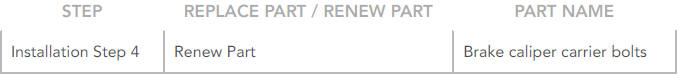
CAUTIONS:
- Do not allow the brake caliper to hang on the brake hose.
- Discard the bolts.
Tie aside.
INSTALLATION
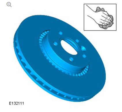
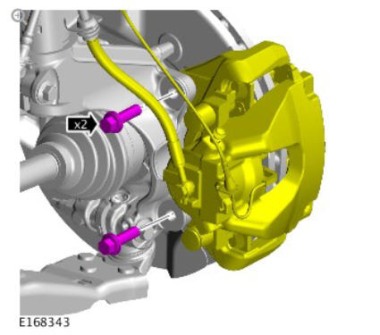
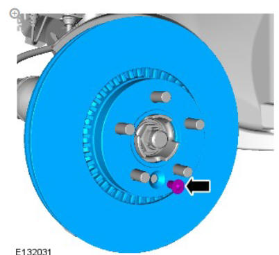
Clean the brake disc using brake cleaning fluid.
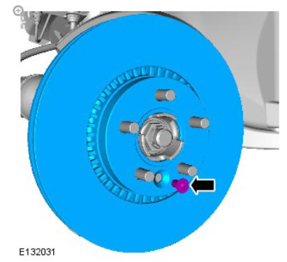
Torque: 35 Nm
WARNING:
Do not use compressed air to clean brake components. Dust from friction materials can be harmful if inhaled.
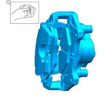
Clean the brake caliper housing and anchor plate using brake cleaning fluid.
CAUTIONS:
- This step only applies to vehicles from VIN H995606 using the M12 fixing.
- Make sure that the brake hose is not twisted and is correctly located.
- Make sure that new bolts are installed.
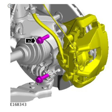
Renew Part: Brake caliper carrier bolts.
Torque:
Stage 1: 90 Nm
Stage 2: 120º
Refer to: Wheel and Tire (204-04 Wheels and Tires, Removal and Installation).
Depress the brake pedal several times, check the fluid level in the brake fluid reservoir and top-up with brake fluid if necessary.
READ NEXT:
 Front Disc Brake Brake Pads (G1785103) / Removal and Installation
REMOVAL
WARNING:
Brake pads must be renewed in axle sets only. Failure to follow this
instruction may result in braking efficiency being impaired.
NOTES:
Left illustration shown, right is similar.
General Information Brake System Bleeding (G1785100) / General Procedures
NOTES:
Bleeding of the complete brake system must be carried out using
Land Rover approved diagnostic equipment. Where only the
primary or secondary brake circuits have been disturbed in
isolatio
General Information Brake System Pressure Bleeding (G1785101) / General
Procedures
BLEEDING
NOTE:
Some variation in the illustrations may occur, but the essential
information is always correct.
All vehicles
WARNING:
Make sure to support the vehicle with axle stands.
Raise and suppor
SEE MORE:
Manual Transmission - Transaxle
External Controls
Gearshift Lever (G1781378)
/ Removal and Installation
REMOVAL
NOTES:
Removal steps in this procedure may contain installation details.
Some variation in the illustrations may occur, but the essential
information is always correct.
NOTE:
Neutral must be selected before the cables are released to
allow the cables to be correctly set on the install.
Sectioned View of Typical
Fuel Fired
Booster Heater
Combustion air fan
Coolant inlet
Coolant outlet
Burner insert
Heat exchanger
Overheat temperature sensor
Exhaust
Fuel inlet
Evaporator
Air inlet
COMBUSTION AIR FAN
The combustion air fan regulates the flow of air into the FFBH to support
combustion of the fuel supplied by the FFBH fuel
