Land Rover Discovery: Driver Door Module / Diagnosis and Testing
PRINCIPLES OF OPERATION
For a detailed description of the Driver Door Module, refer to the relevant Description and Operation section in the workshop manual. REFER to: Handles, Locks, Latches and Entry Systems (501-14 Handles, Locks, Latches and Entry Systems, Description and Operation).
INSPECTION AND VERIFICATION
CAUTION:
Diagnosis by substitution from a donor vehicle is NOT acceptable.
Substitution of control modules does not guarantee confirmation of a fault, and may also cause additional faults in the vehicle being tested and/or the donor vehicle.
NOTES:
- If a control module or a component is suspect and the vehicle remains under manufacturer warranty, refer to the Warranty Policy and Procedures manual, or determine if any prior approval programme is in operation, prior to the installation of a new module/component.
- When performing voltage or resistance tests, always use a digital multimeter accurate to three decimal places, and with an up-todate calibration certificate. When testing resistance always take the resistance of the digital multimeter leads into account.
- Check and rectify basic faults before beginning diagnostic routines involving pinpoint tests.
- Verify the customer concern
- Visually inspect for obvious signs of damage and system integrity
Visual Inspection
.jpg)
- If an obvious cause for an observed or reported concern is found, correct the cause (if possible) before proceeding to the next step
- If the cause is not visually evident, verify the symptom and refer to the Symptom Chart, alternatively check for Diagnostic Trouble Codes (DTCs) and refer to the DTC Index
- Check DDW for open campaigns. Refer to the corresponding bulletins and SSMs which may be valid for the specific customer complaint and carry out the recommendations as required
DTC INDEX
For a list of Diagnostic Trouble Codes (DTCs) that could be logged on this vehicle, please refer to Section 100-00. REFER to: Diagnostic Trouble Code Index - DTC: Driver / Passenger / Rear Left / Rear Right Door Module (DDM/PDM/RLDM/RRDM) (100-00 General Information, Description and Operation).
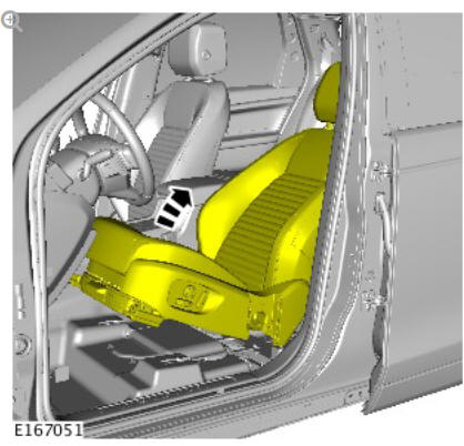
Driver seat module (G1791770) removal and installation
REMOVAL
NOTE:
Removal steps in this procedure may contain installation details.
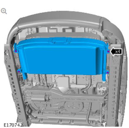
.jpg)
.jpg)
Torque: 40 Nm
.jpg)
.jpg)
Torque: 40 Nm
.jpg)
Reposition the front seat to the central position
Disconnect the battery ground cable.
Refer to: Specifications (414-01, Specifications).
WARNING:
To avoid accidental deployment, the restraints control module backup power supply must be depleted. Wait at least two minutes after disconnecting the battery ground cable(s) before commencing any repair or adjustment to the supplemental restraint system (SRS), or any component(s) adjacent to the SRS sensors. Failure to follow these instructions may result in personal injury.
Make the SRS system safe.
Refer to: Standard Workshop Practices (100-00, Description and Operation).
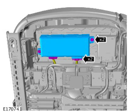
Torque: 6 Nm
INSTALLATION
- To install, reverse the removal procedure.
- If a new component has been installed, configure using Land Rover approved diagnostic equipment.
READ NEXT:
 Keyless Vehicle Module (G2006704) / Removal and Installation
REMOVAL
Disconnect the battery ground cable.
Refer to: Specifications (414-01 Battery, Mounting and Cables,
Specifications).
Remove the loadspace trim panel.
Refer to: Loadspace Trim Panel (50
Navigation System / Diagnosis and Testing
PRINCIPLES OF OPERATION
For a detailed description of the Navigation System, refer to the relevant
Description and Operation section in the workshop manual. REFER to:
Navigation System (415-01 Informa
Passenger Door Module / Diagnosis and Testing
PRINCIPLES OF OPERATION
For a detailed description of the Passenger Door Module, refer to the
relevant Description and Operation section in the workshop manual. REFER
to: Handles, Locks, Latches and E
SEE MORE:
Engine Cooling - Ingenium i4 2.0l Diesel Cooling System Concentration Check
(G2154751) / General Procedures
GENERAL EQUIPMENT
Refractometer / Hydrometer
CHECK
CAUTIONS:
The engine cooling system must be maintained with the correct
concentration and type of anti-freeze solution to prevent corrosion
and frost damage.
Engine coolant will damage the paint finished surfaces. If spilt,
immediately remove
Accessory Drive - Ingenium
i4 2.0l Diesel Accessory
Drive Belt (G1882049)
/ Removal and Installation
REMOVAL
NOTES:
Removal steps in this procedure may contain installation details.
Engine shown removed for clarity.
Disconnect the battery ground cable.
Refer to: Specifications (414-01 Battery, Mounting and Cables,
Specifications).
WARNING:
Make sure to support the vehicle with axle stands.
Rai
