Land Rover Discovery: Keyless Vehicle Module (G2006704) / Removal and Installation
Land Rover Discovery (2009–2016) Service Manual / Electrical / Electronic Feature Group / Keyless Vehicle Module (G2006704) / Removal and Installation
REMOVAL
- Disconnect the battery ground cable.
Refer to: Specifications (414-01 Battery, Mounting and Cables, Specifications).
- Remove the loadspace trim panel.
Refer to: Loadspace Trim Panel (501-05 Interior Trim and Ornamentation, Removal and Installation).
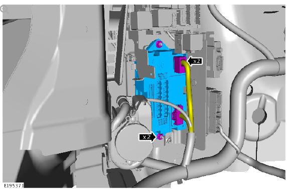
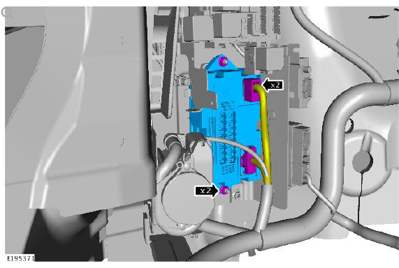
- 1. Remove the wiring harness.
- 2. Remove the 2 nuts.
- 3. Remove the Quiescent Current Control Module
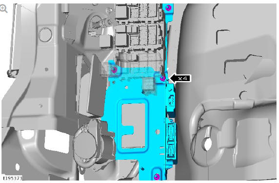
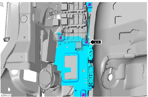
- Remove the 4 nuts.
CAUTION:
Take extra care not to damage the wiring harnesses.
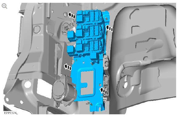
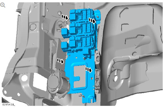
- Remove the rear junction box.
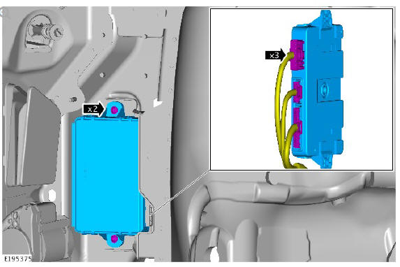
- 1. Remove the 2 bolts.
- 2. Remove the Keyless Vehicle Module.
- 3. Remove the wiring harness.
INSTALLATION

- 1. Install the wiring harness.
- 2. Install the Keyless Vehicle Module.
- 3. Install the 2 bolts.
Torque: 9 Nm
- Install the Rear Junction Box.
- Install the 2 nuts.
Torque: 9 Nm
- 1. Install the Quiescent Current Control Module.
- 2. Install the 2 nuts.
Torque: 9 Nm
- 3. Install the wiring harness.
- Install the loadspace trim panel.
Refer to: Loadspace Trim Panel (501-05 Interior Trim and Ornamentation, Removal and Installation).
- Connect the battery ground cable.
Refer to: Specifications (414-01 Battery, Mounting and Cables, Specifications).
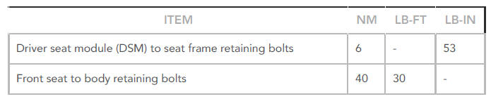
Multifunction electronic modules specifications
Torque Specifications
READ NEXT:
 Navigation System / Diagnosis and Testing
PRINCIPLES OF OPERATION
For a detailed description of the Navigation System, refer to the relevant
Description and Operation section in the workshop manual. REFER to:
Navigation System (415-01 Informa
Passenger Door Module / Diagnosis and Testing
PRINCIPLES OF OPERATION
For a detailed description of the Passenger Door Module, refer to the
relevant Description and Operation section in the workshop manual. REFER
to: Handles, Locks, Latches and E
SEE MORE:
Front Drive Halfshafts Front Right Halfshaft - RHD AWD- lHD AWD (G1794495) -
Removal
SPECIAL TOOL(S)
Removal
CAUTIONS:
Nuts and bolts must be tightened with the weight of the vehicle on
the suspension.
Do not allow halfshafts to hang unsupported at one end or joint
damage will occur.
Make sure the halfshaft constant velocity (CV) joints do not over
articulate. Failure to
Engine - Ingenium i4 2.0l Diesel Lower Timing Chain (G1875890) /
Installation
Installation
Make sure the Fuel pump sprocket is aligned with the timing mark
on the cylinder block.
Install the timing chain.
CAUTION:
Make sure the highlighted links on the timing chain are in line
with the timing marks as illustrated.
Install a new timing chain guide.
Renew Part: Lower t
© 2019-2025 Copyright www.lrdisc.com
