Land Rover Discovery: Anti-Theft - Active/ Description
Description
The door modules provide the interface between the door latch motors, the door and latch switches and the Central Junction Box (CJB). The door modules provide door micro switch status information and enable the door motors on request from the CJB.
The rear door modules are controlled via the front door modules on the Local Interconnect Network (LIN) bus. Additionally, the front door modules also control the exterior mirror functions.
CENTRAL JUNCTION BOX (CJB)
The Central Junction Box (CJB) controls the following functions:
- The horns.
- The tailgate latch motor and micro switches (including the tailgate external release switch).
- The tailgate ajar switch.
- The turn signal indicators.
- The fuel filler flap operation.
The CJB also has a connection to the Restraints Control Module (RCM) for automatic operation of the interior lights and the turn signal indicators in the event of an accident.
NOTE:
If the CJB is replaced, the new module will require configuring to the master car configuration using a Land Rover approved diagnostic system.
The CJB automatically arms and disarms the active anti-theft system when the vehicle is locked and unlocked after successful confirmation that a valid smart key has been used.
INSTRUMENT CLUSTER (IC)
.jpg)
- Alarm Indicator
The Instrument Cluster (IC) controls the alarm indicator which is incorporated in the main display in the IC.
The IC also controls, in conjunction with the Central Junction Box (CJB), the Engine Control Module (ECM) and the ABS control module, the engine immobilization. The ECM controls the engine crank and fuel functions and the ABS control module controls the tilt function. The ECM and ABS control module communicate to each other after the CJB processes the valid smart key information.
Alarm Indicator
The alarm indicator is a Light Emitting Diode (LED) located in the instrument cluster. When the ignition is off, the indicator gives a visual indication of the active anti-theft system to show if the alarm system is set or unset.
When the ignition is on, the indicator provides a visual indication of the status of the passive anti-theft (engine immobilization) system. If the immobilization system is operating correctly, the LED will be illuminated for 3 seconds at ignition on and then extinguish.
If a fault exists in the immobilization system, the LED will be either permanently illuminated or flashing for 60 seconds. This indicates that a fault exists and a fault code has been recorded. After the 60 second period, the LED will flash at different frequencies which indicate the nature of the fault.
Operation of the alarm indicator is controlled by the Instrument Cluster (IC) which varies the flash rate of the LED to indicate the system status of the alarm and the immobilization systems.
.jpg)
.jpg)
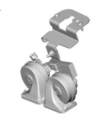
VEHICLE HORNS

The vehicle horns are located above the front bumper armature. The horns are connected directly to the Central Junction Box (CJB) which activates the horns when the alarm is triggered.
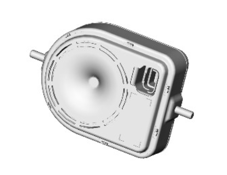
BATTERY BACK UP SOUNDER (BBUS)

The Battery Back Up Sounder (BBUS) is located in the left wheel arch. The sounder is only fitted in certain markets.
On vehicles with a BBUS, a tilt sensor is incorporated which monitors the vehicle attitude. The Central Junction Box (CJB) monitors the tilt sensor and can detect if the vehicle is being moved, towed or raised and activate the alarm.
Operation of the sounder is controlled by the CJB on a Local Interconnect Network (LIN) bus. The sounder is also connected with a permanent battery supply via the CJB. An integral, rechargeable battery powers the sounder if the vehicle battery supply from the CJB is interrupted.
VOLUMETRIC SENSOR
.jpg)
The volumetric sensor is an optional fitment in some markets and is not available in other markets. The volumetric sensor comprises two sensors which allow the interior of the vehicle to be monitored. The module is located in a central position in the front overhead console.
The volumetric sensors are activated with the volumetric mode which in turn is enabled when the vehicle is double locked. The vehicle can be locked and alarmed with the module deactivated if a pet is to be left in the vehicle for example, by single locking the active anti-theft system.
When volumetric mode is active, if the vehicle battery voltage falls to below 9 volts, the Central Junction Box (CJB) will ignore any inputs from the module to prevent false alarm activation.

