Land Rover Discovery: Vehicle Specific Information and Tolerance Checks Fender Alignment
CHECK
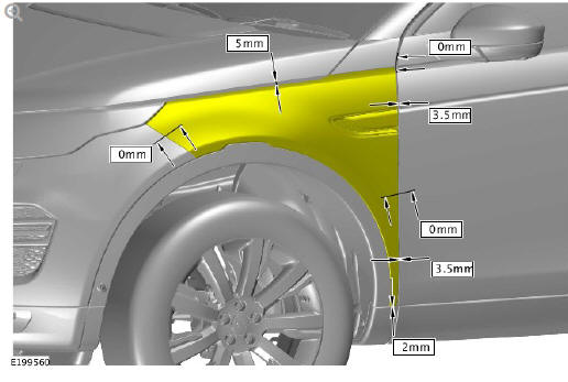
NOTE:
Left illustration shown, right is similar.
.77.jpg)
Check the gap and profiles of the fender are correct.
ADJUSTMENT
Remove the rocker panel moulding.
Refer to: Rocker Panel Moulding (501-08 Exterior Trim and Ornamentation, Removal and Installation).
WARNING:
Make sure to support the vehicle with axle stands.
Raise and support the vehicle.
Remove the front bumper cover.
Refer to: Front Bumper Cover (501-19 Bumpers, Removal and Installation).
Remove the front fender trim panel.
Refer to: Front Fender Trim Panel (501-08 Exterior Trim and Ornamentation, Removal and Installation).
.78.jpg)
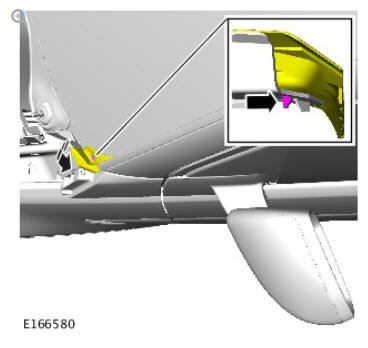
Release the windscreen finisher clip.
.79.jpg)
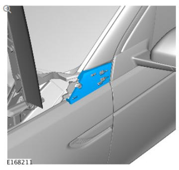
Remove the fender upper finisher.
Torque: 4.1 Nm
.80.jpg)
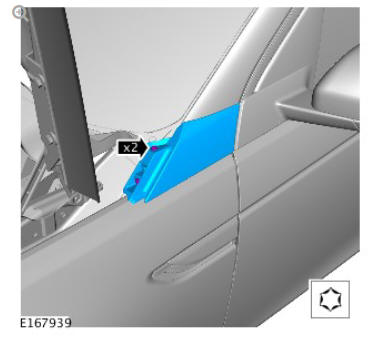
Remove the foam pad.
.81.jpg)
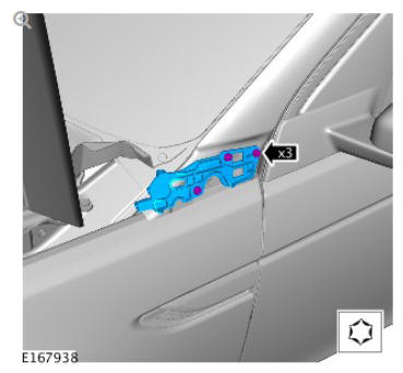
Remove the finisher bracket.
Torque: 4.1 Nm
NOTE:
Loosen the bolts, but do not remove.
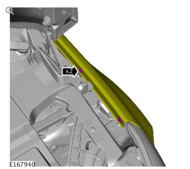
Loosen the two bolts.
Torque: 10 Nm
NOTE:
Loosen the bolts, but do not remove.
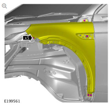
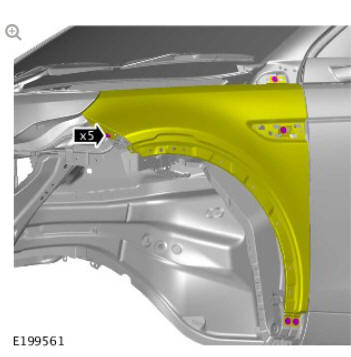
Loosen the five bolts.
Torque: 10 Nm
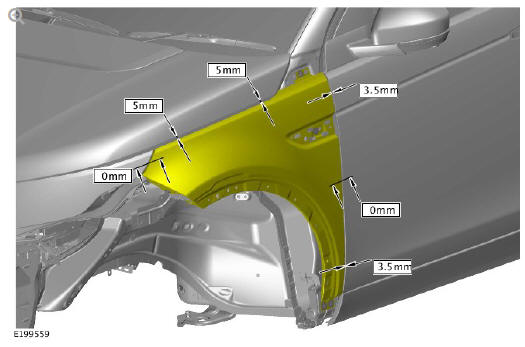
- Align the fender gaps to the surrounding body panels as illustrated.
- Set the fender profiles to the surrounding body panels as illustrated.
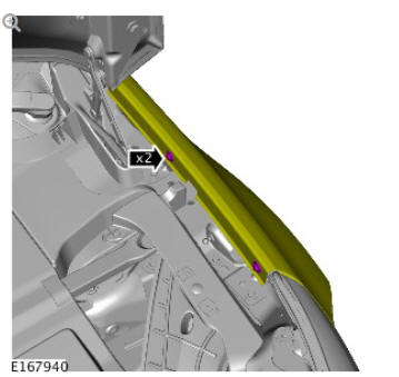
Tighten the two bolts.
Torque: 10 Nm
Tighten the five bolts.
Torque: 10 Nm
Install the finisher bracket.
Torque: 4.1 Nm
Install the foam pad.
Install the fender upper finisher.
Torque: 4.1 Nm
Install the windscreen finisher clip.
Close the hood.
Install the front fender trim panel.
Refer to: Front Fender Trim Panel (501-08 Exterior Trim and Ornamentation, Removal and Installation).
Install the front bumper cover.
Refer to: Front Bumper Cover (501-19 Bumpers, Removal and Installation).
Install the rocker panel moulding.
Refer to: Rocker Panel Moulding (501-08 Exterior Trim and Ornamentation, Removal and Installation).
Check the gap and profiles of the fender are correct.
READ NEXT:
 Side Panel Sheet
Metal Repairs
/ Description and Operation
Side Panel Sheet
Metal Repairs
/ Description and Operation
GALVANIC CORROSION
For additional information, refer to: Corrosion Protection (501-25B,
Description and Operation).
BODY SIDE SERVICE PANELS
TIME SCHEDULES , BODY SIDE SERVICE PANELS
The followi
Side Panel Sheet
Metal Repairs
Side Panel (G1770901)
- Removal
REMOVAL
NOTE:
The side panel is installed in conjunction with:
Front bumper cover
Fender
Fender splash shield
Front fender mounting panel
Windshield
Front door
Rear door
Rocker panel moulding
SEE MORE:
Front Suspension Wheel
Knuckle (G1778608) - Installation
Installation
All vehicles
NOTE:
This step is only required if previously removed.
Vehicles with dynamic suspension
Remove the special tool.
CAUTION:
Install a new retaining bolt and nut.
Renew Part: Wheel knuckle nut and bolt.
Torque:
Stage 1: 80 Nm
Stage 2: 180º
CAUTION:
Make sure the wi
Fuel Charging and Controls
- Ingenium i4 2.0l Diesel
Fuel Injectors (G1875958)
/ Removal and Installation
SPECIAL TOOL(S)
PART(S)
REMOVAL
WARNINGS:
Place the vehicle in a well ventilated, quarantined area and
arrange
' No Smoking/Petrol Fumes' signs about the vehicle.
Avoid flames, sparks or lighted substances.
Be prepared to collect escaping fuel.
It is imperative that new high pressure fu
