Land Rover Discovery: Side Panel Sheet Metal Repairs 'A' Pillar Outer Panel (G1770902) - Installation
Installation
- Dress the flanges where necessary.
.101.jpg)
- Mark out the position on the new A-pillar outer panel where the upper and lower Metal Inert Gas (MIG) welded butt joints are to be made. Cut through the new panel as indicated.
- Offer up the new A-pillar outer panel and clamp into position.
Check alignment if correct, proceed to next step, if not, rectify and recheck before proceeding.
NOTE:
Follow Steps 1 to 3 as shown above to cut the MIG braze slots.
.102.jpg)
Cut slots in the new A-pillar outer panel where the MIG braze slot welds are to be installed as indicated.
NOTE:
Follow Steps 1 and 2 as shown above to cut the MIG braze slots.
.103.jpg)
- Cut slots in the new A-pillar outer panel where the MIG braze slot welds are to be installed as indicated.
.104.jpg)
- Drill holes in new A-pillar outer panel where the MIG plug welds are to be installed as indicated.
.105.jpg)
- Drill holes in new A-pillar outer panel where the MIG plug welds are to be installed as indicated.
- Remove the new A-pillar outer panel.
- Deburr the drilled holes.
- Prepare the old and new panel joint surfaces including the Noise, Vibration and Harshness (NVH) components.
- Apply a 5 mm bead of Land Rover approved sealer adhesive to the NVH components as indicated.
.106.jpg)
- Offer up the new A-pillar outer panel and clamp into position.
Check alignment if correct, proceed to next step, if not, rectify and recheck before proceeding.
NOTE:
Make sure that spot welds are installed at least 5 mm away from existing spot welds on underlying panels.
.107.jpg)
- Install the spot and MIG plug welds as indicated.
.108.jpg)
- Install the MIG braze slot welds as indicated.
.109.jpg)
- Install the MIG braze slot welds as indicated
NOTE:
Make sure that spot welds are installed at least 5 mm away from existing spot welds on underlying panels.
.110.jpg)
- Install the spot and MIG plug welds as indicated.
.111.jpg)
- Install the spot welds as indicated.
.112.jpg)
- MIG weld the butt joints as indicated.
- Dress all welds.
- Install the door hinges and tighten the bolts to 30 Nm.
- Apply a Land Rover recommended sealer and seal the panel flange edges of the MIG braze slot welds in the door aperture area to prevent water ingress
- Apply a Land Rover recommended sealer and seal the front flange of the A-pillar outer above the fluting to prevent water ingress.
- Make sure that any open or exposed panel joints are correctly sealed.
- Make sure corrosion protection is applied to all areas affected by repair.
- The installation of associated panels and components is the reversal of removal procedure.
Roof Sheet Metal Repairs / Description and Operation
GALVANIC CORROSION
For additional information, refer to: Corrosion Protection (501-25B Body Repairs - Corrosion Protection, Description and Operation).
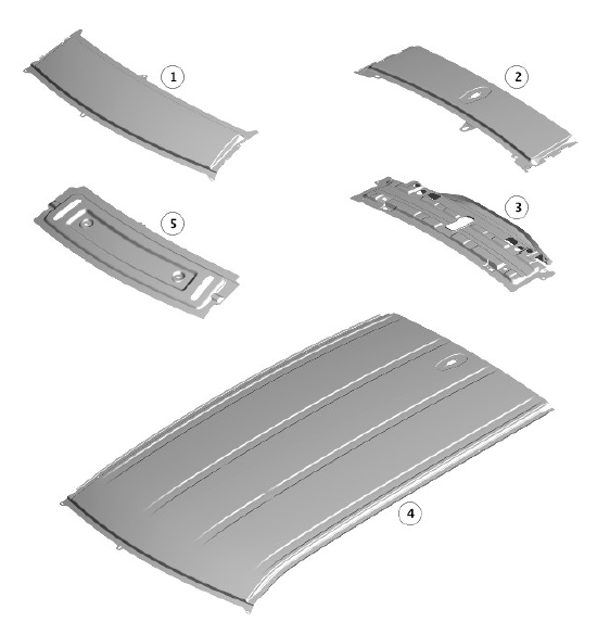
ROOF SERVICE PANELS

.113.jpg)
TIME SCHEDULES , ROOF SERVICE PANELS
The following information shows the total time taken to install single panels.
These times do not include removal of mechanical, electrical and trim, (MET), items or paint times.
The times shown are to be used as a guide only.
.114.jpg)

