Land Rover Discovery: Power Steering - Description
Steering Gear
.jpg)
- Recirculating ball nut
- Steering rack
- Pinion shaft
- Torque sensor
- Boot (2 off)
- Track rod (2 off)
- Threaded boss for securing bolt (2 off)
- Signal and power lead for torque sensor
- Power Steering Control Module (PSCM)
- Electric motor
- Drive belt
- Reduction gear housing
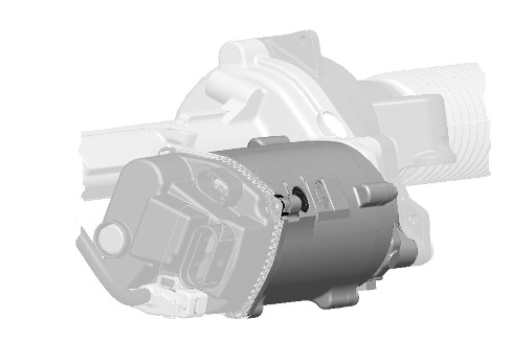
The steering gear is installed on the front subframe. A yoke connects the input shaft of the steering gear to the bottom of the steering column. A rubber seal assembly is installed on the input shaft where it passes through the vehicle's lower firewall. Ball jointed tie-rods connect the steering rack to the knuckles of the front suspension. The ends of the steering rack are protected by corrugated rubber boots secured with band clamps. A heat shield is attached to the top of the steering gear to reflect radiant heat from the exhaust system.
The steering rack is installed in a steering gear housing that also contains the pinion shaft and the torque sensor. A torsion bar connects the pinion shaft to the input shaft. The steering gear housing also incorporates a mounting for the electric motor, and two threaded bosses for the steering gear securing bolts. A reduction gear housing, on the end of the steering gear housing, contains a recirculating ball nut installed on a threaded section of the steering rack. A toothed belt transmits drive from the electric motor to the recirculating ball nut to provide the power assistance.
Electric Motor

The electric motor is a brushless Direct Current (DC) motor. The electronics that convert the DC power supply into phase voltages are contained in the PSCM.
Motor Position Sensors
Motor position is detected by magnetic sensors in the PSCM, adjacent to rotating magnets on the electric motor shaft. From the position of the electric motor, the PSCM can determine the position of the road wheels and the steering angle.
After first calibrating with the steering angle sensor, the PSCM subsequently uses the motor position sensor inputs for control of the power steering.
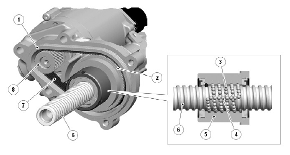
Reduction Gear

- Reduction gear housing
- Ball nut drive gear
- Ball train
- Ball return channel
- Ball nut
- Steering rack ball channel
- Drive belt
- Motor drive gear
The recirculating ball nut in the reduction gear housing is held in a bearing race, allowing the nut to rotate but preventing it from moving axially. As the electric motor rotates the nut, the balls are driven along the channels in the nut and the steering rack, and produce an axial force on the steering rack. A channel in the nut, and mechanisms at either end of the bearing race, recirculate the balls from one side of the nut to the other.
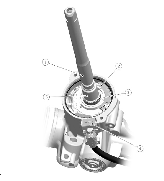
Torque Sensor

- Torsion bar (not visible)
- Sensor electronics
- Magnet
- Sensor connector
- Input shaft
The torque sensor provides the PSCM with inputs of the steering torque applied by the driver. The torque sensor is installed at the junction between the input shaft and the pinion shaft, inside the steering gear housing.
Torque applied to the input shaft is transferred to the pinion shaft through the torsion bar, which twists under load. The torque sensor calculates the amount of twist in the torsion bar using a Hall effect sensor to monitor the angular position of the input shaft in relation to the pinion shaft, then transmits the result in a digital signal to the PSCM.
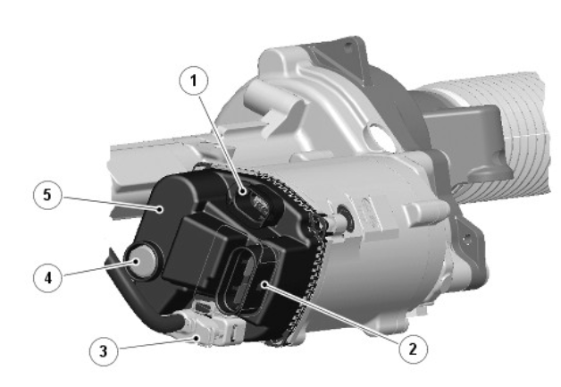
Power Steering Control Module

- Power Steering Control Module (PSCM) system connector (connection for CAN communication)
- Electric motor power supply connector
- Torque sensor connector
- Diaphragm
- Power steering control module cover
The Power Steering Control Module (PSCM) is located on the end of the electric motor, under a hermetically sealed cover. A diaphragm in the cover, made from a waterproof breathable fabric, maintains the interior of the cover at ambient pressure, avoiding the need for an open vent.
As well as the control circuitry, the PSCM also contains the power electronics for operating the electric motor.
Power assistance is provided when the following are present:
- A permanent live feed from the Battery Junction Box (BJB) (see description below).
- An ignition feed from the ignition relay in the Central Junction Box (CJB).
- The power mode Controller Area Network (CAN) bus signal is set to engine running.
Electrical power for operation of the electric motor is provided by a permanent feed from the BJB. For 100% nominal power assistance, supply voltage must be between 10.5 and 18 V. If supply voltage is outside of these limits, power assistance is either reduced or discontinued.
The PSCM receives hardwired digital inputs from the torque sensor and high speed CAN bus inputs of:
- Steering angle, from the steering angle sensor.
- Engine speed, from the Engine Control Module (ECM), via the GateWay Module (GWM). For additional information, refer to: Electronic Engine Controls (303-14A Electronic Engine Controls - TD4 2.2L Diesel, Description and Operation), Electronic Engine Controls (303-14C Electronic Engine Controls - GTDi 2.0L Petrol/GTDi 2.0L Petrol - SULEV, Description and Operation).
- Vehicle speed and yaw rate, from the Anti-lock Brake System (ABS)
control module.
For additional information, refer to: Anti-Lock Control - Traction Control (206-09B Anti-Lock Control - Traction Control, Description and Operation).
- Automatic steering requests, from the Parking Aid Control Module
(PACM) (if park assist system is fitted).
For additional information, refer to: Parking Aid (413-13 Parking Aid, Description and Operation).
- Reverse gear signal from the CJB, through the GWM (manual transmission only).
- Terrain mode request from the Terrain Response.
For additional information, refer to: Four-Wheel Drive Systems (308-07A Four-Wheel Drive Systems - Vehicles With: Active Driveline, Description and Operation).
- Vehicle speed from the Transmission Control Module (TCM), through the
GWM (automatic transmission only).
For additional information, refer to: Transmission Description (307-01 Automatic Transmission/Transaxle, Description and Operation).
- Power mode from the CJB via the GWM.
- Eco stop/start system stop request from the ECM, through the GWM (if stop/start system is fitted). For additional information, refer to: Starting System (303-06A Starting System - TD4 2.2L Diesel, Description and Operation), Starting System (303-06C Starting System - GTDi 2.0L Petrol/GTDi 2.0L Petrol - SULEV, Description and Operation).
- Lane departure warning haptic steering wheel vibration request from the
Auto High Beam Control Module (AHBCM).
For additional information, refer to: Warning Devices (413-09 Warning Devices, Description and Operation).
The Power Steering Control Module (PSCM) uses the input data and software algorithms to control electric motor operation. If required, the PSCM can also transmit outputs, on the high speed CAN Chassis bus, of:
- Warning status, to the Instrument Cluster (IC) through the GWM.
- Steering status, to the PACM (if park assist system fitted) and Terrain Response.
- Eco stop/start system engine stop inhibit and engine restart requests to the ECM through the GWM.
REDUCED ASSISTANCE WARNING INDICATION
If there is a significant reduction in power assistance, the amber general warning indicator illuminates and a warning message is displayed in the message centre. When the warning message is first displayed, the IC produces a single alert chime.
For additional information, refer to: Instrument Cluster (413-01 Instrument Cluster, Description and Operation).
If the steering gear is replaced, the warning will be activated until the appropriate configuration of the electric power steering has been completed.
The symptom driven diagnostics tool must be used to diagnose Power Steering issues, only if directed by diagnostic tools should a gear be replaced.
FREEZING PREVENTION WARNING INDICATOR
The PSCM has detected that water has penetrated the electric power steering gear and is beginning to freeze. An electric power steering motor vibration is initiated. Whilst the vibration is present the amber general warning indicator illuminates and a warning message 'Steering vibration activated. Drive with care' is displayed in the message centre. When the warning message is first displayed, the IC produces a single alert chime.
For additional information, refer to: Information and Message Center (413- 08 Information and Message Center, Description and Operation).

