Land Rover Discovery: Power Bbrake Actuation / Description and Operation
COMPONENT LOCATION
BRAKE BOOSTER COMPONENT LOCATION
NOTE:
Right Hand Drive (RHD) illustrations shown, Left Hand Drive (LHD) illustrations similar
TD4 2.2L Engine with Stop/Start
.jpg)
- Brake booster
- Brake vacuum switch
- Brake booster connector
- Vacuum pipe
- Non-return valve
- Vacuum pump
TD4 2.2L Engine without Stop/Start
.jpg)
- Brake booster
- Brake booster connector
- Vacuum pipe
- Non-return valve
- Vacuum pipe
GTDi 2.0L Engine with Stop/Start
.jpg)
- Brake booster
- Brake vacuum switch
- Brake booster connector
- Vacuum pipe
- Non-return valve (2 of)
- Vacuum pump
GTDi 2.0L Engine without Stop/Start
.jpg)
- Brake booster
- Brake booster connector
- Vacuum pipe
- Non-return valve (2 of)
- Vacuum pump
OVERVIEW
Power assistance for the braking system is provided by a vacuum operated, non-active brake booster. The vacuum required for brake booster operation is created by an engine driven vacuum pump.
Rigid plastic piping connects the vacuum pump to the brake booster.
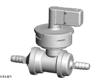
Vehicles fitted with the stop/start system incorporate a brake vacuum switch in the piping. A non-return valve is installed in the piping to maintain the vacuum necessary for brake booster operation.
On the GTDi 2.0L Engine variant, there are non return valves fitted to maintain vacuum for brake booster operation.
DESCRIPTION
BRAKE BOOSTER
.jpg)
The brake booster is a compact unit that occupies less space than a conventional brake booster, improving the vehicles crash performance characteristics. The unit is installed with tandem diaphragms that are 203.20mm (8.00in) and 228.60mm (9.00in) in diameter and operate as a single unit.
VACUUM PUMP

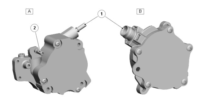
- Vacuum pump - TD4 2.2L Engines
- Vacuum pump - GTDi 2.0L Engines
- Brake booster port
- Exhaust Gas Recirculation (EGR) port
For both TD4 2.2L and GTDi 2.0L engines, the vacuum pump is attached to the rear of the engine and driven by the intake camshaft.
On the TD4 2.2L engine, the vacuum pump has an additional vacuum port, which is connected to the Exhaust Gas Recirculation (EGR) system.
For additional information, refer to: Engine Emission Control (303-08A Engine Emission Control - TD4 2.2L Diesel, Description and Operation).
BRAKE VACUUM SWITCH

The brake vacuum switch monitors vacuum reserves in the brake booster and is hardwired to the Engine Control Module (ECM). The ECM supplies a 5V reference voltage to the switch and monitors the return signal to determine the pressure in the brake booster.
Power brake actuation specifications
General specification
.jpg)
Torque specification
.jpg)

