Land Rover Discovery: Rear Disc Brake Brake Caliper (G1785110) - Removal
REMOVAL
CAUTION:
If brake fluid is spilt on the paintwork, the affected area must be immediately washed down with cold water.
NOTE:
Removal steps in this procedure may contain installation details.
Connect the diagnostic tool and set the electronic park brake (EPB) to the maintenance position.
NOTE:
This step is only required if the diagnostic tool is not available.
Refer to: Electronic Parking Brake Service Mode Activation and Deactivation (206-05 Parking Brake and Actuation, General Procedures).
NOTE:
This step is only required if the vehicle has no battery power.
Refer to: Electronic Parking Brake Release When the Vehicle Has No Electrical Power (206-05 Parking Brake and Actuation, General Procedures).
WARNING:
Make sure to support the vehicle with axle stands.
Raise and support the vehicle.
Refer to: Rear Wheel Arch Liner (501-08 Exterior Trim and Ornamentation, Removal and Installation).
.jpg)
.jpg)
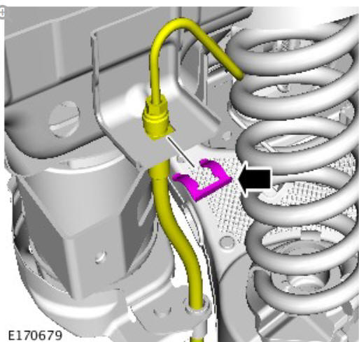
CAUTIONS:
- Be prepared to collect escaping fluids.
- If the brake hose banjo bolt has been loosened or removed, a new brake hose assembly must be installed.
- Make sure that all openings are sealed. Use new blanking caps.
NOTE:
The flexible brake hose with washers and the banjo bolt is only available as an assembly.
.jpg)
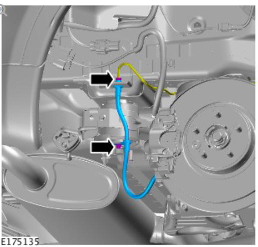
CAUTION:
Make sure that all openings are sealed. Use new blanking caps.
.jpg)
CAUTION:
Remove and discard the O-ring seal.
NOTE:
Do not disassemble further if the component is removed for access only.
.jpg)
READ NEXT:
 Rear Disc Brake Brake Caliper (G1785110) - Installation
CAUTION:
A new O-ring seal is to be installed.
NOTE:
This step is only required if previously removed.
Torque: 11 Nm
Torque: 28 Nm
NOTE:
Remove and discard all blanking caps.
Torque:
Line union
Rear Disc Brake Brake Caliper Anchor Plate (G1785111) / Removal and
Installation
PART(S)
REMOVAL
NOTE:
Removal steps in this procedure may contain installation details.
Connect the diagnostic tool and set the electronic park brake (EPB)
to the maintenance position
NOTE:
This
Rear Disc Brake Brake Disc (G1785109) / Removal and Installation
PART(S)
REMOVAL
NOTE:
Removal steps in this procedure may contain installation details.
Connect the diagnostic tool and set the electronic park brake (EPB)
to the maintenance position.
NOTE:
This ste
SEE MORE:
Spring and Shock Absorber
NOTE:
Adaptive dynamics damper shown, standard damper similar.
Bolt - shock absorber to wheel knuckle
Shock absorber
Nut - Shock absorber top mounting to body fastener
Nut - shock absorber to top mounting.
Spring isolator
Spring
Nut - shock absorber to wheel knuckle
Spring
The coil spring
Glow Plug System - Ingenium i4 2.0l Diesel
/ Diagnosis and Testing
PRINCIPLES OF OPERATION
For a detailed description of the Glow Plug System, refer to the relevant
Description and Operation section in the workshop manual. REFER to: Glow
Plug System (303-07B Glow Plug System - INGENIUM I4 2.0L Diesel,
Description and Operation).
INSPECTION AND VERIFICATION
CAUTION:
