Land Rover Discovery: Fuel Tank Draining (G898063) / General Procedures
WARNINGS:
- Place the vehicle in a well ventilated, quarantined area and arrange ' No Smoking/Petrol Fumes' signs about the vehicle.
- Do not carry or operate cellular phones when working on or near any fuel related components. Highly flammable vapors are always present and may ignite. Failure to follow these instructions may result in personal injury.
- Do not smoke or carry lighted tobacco or open flame of any type when working on or near any fuel related components. Highly flammable vapors are always present and may ignite. Failure to follow these instructions may result in personal injury.
- The spilling of fuel is unavoidable during this operation. Ensure that all necessary precautions are taken to prevent fire and explosion.
CAUTION:
Before disconnecting or removing components, ensure the area around the joint faces and connections are clean. Plug open connections to prevent contamination.
NOTE:
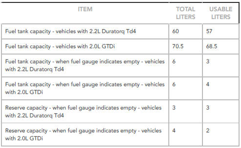
It is possible that up to 2 litres of fuel may be left in the tank after draining.
- Open the fuel filler door and remove the cap.
- Disconnect the battery ground cable. Refer to: Specifications (414-01 Battery, Mounting and Cables, Specifications).
- Connect the fuel tank drain equipment ground cable to the vehicle.
WARNING:
Fuel may still be present in the fuel tank after draining.
Remove the fuel from the fuel tank, via the filler neck, using the fuel tank draining equipment. Follow the manufacturer's operating instructions.
To install, reverse the removal procedure.
General Information Diesel Filter Water Drain-off (G1450064) General Procedures
DRAINING
WARNINGS:
- Avoid flames, sparks or lighted substances.
- Wait for a minimum of 1 minute after the engine has stopped before carrying out any repair to the fuel injection system.
CAUTION:
Make sure that the area around the component is clean and free of foreign material.
Refer to: Engine Cover - TD4 2.2L Diesel (501-05 Interior Trim and Ornamentation, Removal and Installation).
WARNING:
Make sure to support the vehicle with axle stands.
Raise and support the vehicle.
Refer to: Engine Undershield (501-02 Front End Body Panels, Removal and Installation).
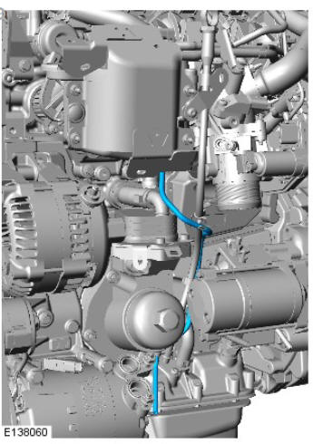
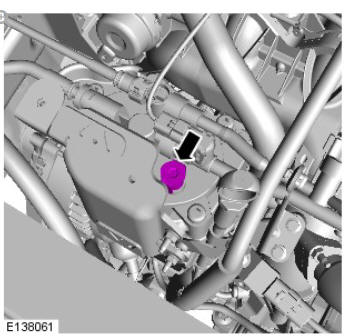
Position a container to collect the fluid.
CAUTION:
Make sure that all fluid is drained from the fuel filter.
FILLING
WARNINGS:
- Avoid flames, sparks or lighted substances.
- Wait for a minimum of 1 minute after the engine has stopped before carrying out any repair to the fuel injection system.
CAUTION:
Make sure that the area around the component is clean and free of foreign material.
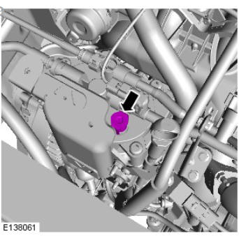
Remove the container.
Refer to: Engine Undershield (501-02 Front End Body Panels, Removal and Installation).
Refer to: Engine Cover - TD4 2.2L Diesel (501-05 Interior Trim and Ornamentation, Removal and Installation).
Refer to: Fuel System Bleeding - TD4 2.2L Diesel (310-00 Fuel System - General Information, General Procedures).
General Information Fuel System Bleeding - Ingenium i4 2.0l Diesel (G1801385) General Procedures
WARNING:
After carrying out repairs, the fuel system must be checked visually for leaks. Failure to follow this instruction may result in personal injury.
NOTE:
This procedure is necessary if any low-pressure fuel system components are removed or replaced. These include the fuel filter, fuel lines, fuel tank or fuel cooler.
CAUTION:
Do not start the engine.
- Set the ignition to the ON position.
- Wait for 65 seconds.
- Set the ignition to the OFF position.
- Repeat the above steps 2 more times.
Start the engine and idle for 60 seconds
General Information Specifications
Capacities
READ NEXT:
 Clutch / Description and Operation
COMPONENT LOCATION
Clutch pedal
Brake/clutch reservoir
Brake fluid level sensor
High pressure clutch line
Clutch master cylinder
Clutch pedal position sensor
Low pressure hose connector
Low
Clutch System Bleeding
(G1353044) / General Procedures
GENERAL EQUIPMENT
Brake/clutch system pressure bleeder/filler
WARNING:
Do not allow dirt or foreign liquids to enter the reservoir. Use
only
new brake fluid of the correct specification from airtight
SEE MORE:
Diagnosis and Testing Information and Entertainment System
PRINCIPLE OF OPERATION
For a detailed description of the information and entertainment system,
refer to the relevant description and operation sections in the workshop
manual.
INSPECTION AND VERIFICATION
CAUTION:
Diagnosis by substitution from a donor vehicle is NOT acceptable.
Substitution of cont
Wheel changing safety
Before raising the vehicle or changing a
wheel, make sure that you read and
comply with the following warnings:
Always find a safe place to stop;
off the highway and away from
traffic.
Do not jack the vehicle if it is over
a metal grating or manhole cover.
Make sure the vehicle is on firm,
l
