Land Rover Discovery: Clutch / Description and Operation
COMPONENT LOCATION
.jpg)
- Clutch pedal
- Brake/clutch reservoir
- Brake fluid level sensor
- High pressure clutch line
- Clutch master cylinder
- Clutch pedal position sensor
- Low pressure hose connector
- Low pressure hose
- Clutch bleed
- Transmission
- Clutch slave cylinder
- Clutch cover assembly
- Dual Mass Flywheel
- Clutch driven plate
- Clutch cover assembly mounting bolt (6 off)
OVERVIEW
The clutch is a self-adjusting type, with a single stage damped clutch driven plate and a spring clutch cover assembly which is hydraulically actuated from the clutch pedal.
The main components of the clutch are the clutch cover assembly (pressure plate), the engine dual mass flywheel and the clutch driven plate (friction plate). Together with the dual mass flywheel and drive plate, the clutch cover assembly forms a friction system and is mounted to the dual mass flywheel by bolts in the housing.
DESCRIPTION
Clutch Cover Assembly
.jpg)
- Pressure plate
- Straps (3 off)
- Fixings (6 off)
- Diaphragm spring
- Clutch cover assembly
The clutch cover assembly ensures that the engine torque is transferred via the drive plate to the transmission input shaft. The contact force required for transferring engine torque is provided by a slotted diaphragm spring.
The diaphragm spring allows the driver to apply less pressure on the clutch pedal due to low release force. A pressure plate provides the friction surface for the drive plate to engage on.
The diaphragm spring is of the compressed type which is actuated by the clutch slave cylinder. When the clutch slave cylinder is operated, the force from the diaphragm spring is transferred through the clutch cover assembly into the dual mass flywheel it is bolted to, releasing the pressure on the clutch driven plate and disengaging the drive to the transmission.
The clutch cover assembly is attached to the clutch housing by straps. The diaphragm spring is located in the cover housing between the fulcrum ring and support ring, which is riveted to the housing. The self-adjusting mechanism is located between the diaphragm spring and pressure plate. As the drive plate wears the self-adjust mechanism adjusts to keep the diaphragm spring in the same position, keeping the clamp load and release load constant over lifetime.
Clutch Driven Plate

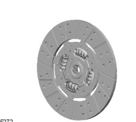
The clutch driven plate is the central connection element in the clutch. In combination with the clutch cover assembly, it separates and links engine and powertrain by connecting the engine crankshaft to the transmission input shaft.
The clutch driven plate is a single stage damped type friction plate with a compound organic resin friction material. The splined hub is attached to the disc with four springs to damp driveline vibrations. The vibrational damping system consists of a friction unit and spring sets for both driving and idling.
Coil springs positioned in windows allow a limited degree of rotation between the crankshaft and the transmission input shaft. The splined hub mates with corresponding splines on the transmission input shaft.
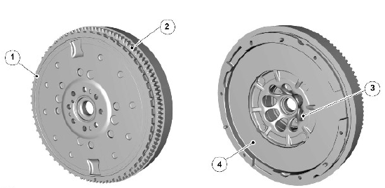
Dual Mass Flywheel

- Crank sensor reluctor ring
- Ring gear (primary side)
- Crankshaft mounting holes (8 off)
- Friction surface (secondary side)
The dual mass flywheel comprises two main components; the primary side which is attached to the engine crankshaft and the secondary side to which the clutch cover assembly is attached.
The primary side has the starter ring gear and crankshaft position sensor reluctor ring attached to its outer circumference. The ring gear is used by the starter motor to rotate the engine during engine crank at start up. The crankshaft position sensor reluctor ring provides the target for the crank sensor for engine timing. The primary side is secured to the crankshaft with eight bolts. A dowel in the crankshaft flange ensures that the dual mass flywheel is correctly located.
The secondary side has the smooth friction surface on which the clutch driven plate friction material engages. Dowels and threaded fixing holes allow for the correct alignment and attachment of the clutch cover assembly.
The primary and secondary sides are connected with long coil springs. The two sides can rotate against each other, limited spring shoes within the flywheel. The springs absorb torque loading on clutch engagement and disengagement. The secondary side also incorporates a centrifugal pendulum vibration absorber, which working with the coil springs reduces torsional vibrations from the engine.
OPERATION
When the clutch pedal is not being operated, the clutch provides a friction drive between the dual mass flywheel and the clutch cover assembly. The contact force to produce the required friction is provided by diaphragm springs in the clutch cover assembly.
Operation of the clutch pedal produces hydraulic pressure in the clutch master cylinder which is passed via pipes to the clutch slave cylinder. When the clutch slave cylinder is operated, the cylinder piston moves, the pressure on the diaphragm springs is released and the clutch cover assembly pressure plate lifts releasing the pressure on the clutch driven plate surface allowing the clutch driven plate to disengage the drive between the engine crankshaft and the transmission.
Clutch Specifications
Lubricants, Fluids, Sealers and Adhesives
.jpg)
General Specification
.jpg)
Torque Specifications
.jpg)
* Tighten bolts progressively by diagonal selection.

