Land Rover Discovery: Fuel Pump Driver Module

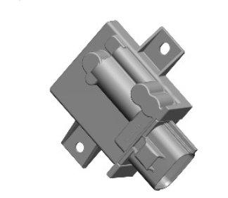
The fuel pump operation is regulated by the FPDM which is controlled by the Powertrain Control Module (PCM). The FPDM regulates the flow and pressure supplied by controlling the operation of the Low Pressure (LP) fuel pump using a Pulse Width Modulation (PWM) output.
The FPDM is powered by a supply from the fuel pump relay in the Rear Junction Box (RJB). The LP fuel pump relay is energized on opening the driver's door, pressing the start button only or pressing the start button and the footbrake (which initiates engine cranking). The FPDM supplies power to the LP fuel pump, and adjusts the power to control the speed of the LP fuel pump and the pressure and flow in the fuel delivery line.
A PWM signal from the PCM tells the FPDM the required speed for the LP fuel pump. The on time of the PWM signal represents half the LP fuel pump speed, for example; if the PWM signal has an on time of 50 %, the FPDM drives the pump at 100 %.
The FPDM will only energize the LP fuel pump if it receives a valid PWM signal, with an on time of between 4 % and 50 %. To switch the LP fuel pump off, the PCM transmits a PWM signal with an on time of 75 %.
The output pressure from the LP fuel pump will change with changes of engine demand and fuel temperature. The PCM calibrates the engine and fuel demands then sends a PWM signal to the FPDM to adjust the speed of the LP fuel pump as necessary.
If the PCM does not detect pressure in the fuel delivery line, it stops, or refuses to start the engine and stores the appropriate Diagnostic Trouble Code (DTC).
The PCM receives a monitoring signal from the FPDM. Any DTCs produced by the FPDM are stored by the PCM.
DTCs can be retrieved from the PCM using an approved diagnostic system.
The FPDM itself cannot be interrogated by the approved diagnostic system.
OPERATION
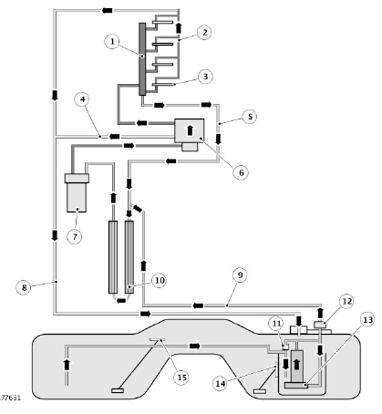
Fuel System Flow Schematic

- Fuel rail
- Injector leak-off return line
- Fuel injector (4 off)
- High Pressure (HP) fuel pump return line
- Fuel rail return line
- HP fuel pump (engine mounted)
- Fuel filter assembly
- Fuel return/air bleed pipe
- Low pressure (LP) delivery pipe
- Fuel cooler
- Jet pump
- Pressure regulator
- Fuel pump module
- Active fuel level sensor 'A'
- Passive fuel level sensor 'B'
The Low Pressure (LP) fuel pump operation is regulated by the Fuel Pump Driver Module (FPDM), which is controlled by the Powertrain Control Module (PCM). The FPDM regulates the fuel flow and pressure delivered to the engine mounted High Pressure (HP) fuel pump by controlling the operation of the LP fuel pump using a Pulse Width Modulation (PWM) output.
The FPDM has a power supply connection from the Battery Junction Box (BJB) via the LP fuel pump relay. The LP fuel pump relay is controlled by the Central Junction Box (CJB) and it is active when the ignition is switched on (power mode 6).
Inside the fuel tank there are two fuel level sensors; 'A' and 'B', which output signals to the CJB for fuel tank fuel level. This information is processed by the CJB and passed to the Instrument Cluster (IC) to display the remaining fuel level and low fuel warning.
INPUT/OUTPUT DIAGRAM
NOTE:
A = Hardwired; AL = PWM (Pulse Width Modulation); AN = High Speed (HS) Controller Area Network (CAN) powertrain systems bus
.jpg)
- Fuel Pump Driver Module (FPDM)
- Powertrain Control Module (PCM)
- Instrument Cluster (IC)
- Central Junction Box (CJB)
- Fuel Pump Module
- Ground
- Power supply

