Land Rover Discovery: Engine Emission Control - Ingenium i4 2.0l Diesel / Description and Operation
COMPONENT LOCATION
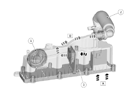
.jpg)
- Positive Crankcase Ventilation Valve
- Breather Pipe
- Engine vent module
- Positive Crankcase Ventilation Baffle
Exhaust Gas Recirculation EU5 and EU6
.jpg)
- High Pressure (HP) Exhaust Gas Recirculation (EGR) valve motor
- High Pressure (HP) Exhaust Gas Recirculation (EGR) outlet to intake manifold
- Exhaust Gas Recirculation (EGR) tube from exhaust manifold
- Air inlet from air filter
- Breather pipe inlet from engine vent module
- Turbocharger attachment
- Engine coolant connection
- Diesel Particulate Filter (DPF) connection
- EGR cooler with differential pressure sensor
- EGR tube assembly
OVERVIEW
Exhaust Gas Recirculation EU5 and EU6
Engine Emissions
The engine emission control system reduces the level of hydrocarbon emissions released to the atmosphere from the engine.
The engine emission control system consists of an oil separator and Positive Crankcase Ventilation valve located on the engine vent module.
Piston blow-by gases are drawn through the Positive Crankcase Ventilation valve into the engine air intake.
The resultant depression in the engine oil pan, front covers and camshaft covers reduces the load on the joint seals in those areas
Exhaust Gas Recirculation
The exhaust gas recirculation (EGR) reduces the oxides of nitrogen (NOX) emissions from the engine by passing the exhaust gases back through the engine via the intake manifold.
This reduces the amount of oxygen in the intake air which reduces the creation of NOX as part of the combustion process.
NOx is formed by the naturally occurring Nitrogen in the air and the oxygen burning at high temperatures. By recirculating the exhaust gasses the ignition temperature in the engine is reduced, reducing the production of NOx.
DESCRIPTION

OIL SEPARATOR
- Gas and Oil Vapor
- Gas Vapor
- Positive Crankcase Ventilation Valve
- Breather Pipe
- Positive Crankcase Ventilation Baffle
Oil Separator
The breather consists of an oil separator, Positive Crankcase Ventilation valve and a flexible hose. The oil separator and the Positive Crankcase Ventilation valve are installed in the top of the Engine Vent Module. The flexible hose connects to the turbocharger input duct connector.
The oil separator is installed in a channel in the top of the engine vent module. A baffle plate, which incorporates a gas intake and an oil drain, is installed over the channel.
The gas and oil vapor pass over the separator. The oil drains to the camshaft carrier. The vapor is drawn into the turbocharger via a flexible hose attached to the turbocharger inlet duct from the engine vent module.
The Positive Crankcase Ventilation valve regulates the crankcase pressure.
Exhaust Gas Recirculation
There are two main external Exhaust Gas Recirculation (EGR) systems that are used on the engine.
- High Pressure (HP) EGR
- Low Pressure (LP) EGR
EGR is used to cool the combustion in the cylinders by introducing exhaust gases without oxygen (exhaust gas). This in turn allows the use of smaller fuel injections, improving emissions and fuel economy.
The following system is used for specific markets
- EU5/6 markets - use both HP and LP EGR valves. The LP system uses an EGR cooler, there is no cooler for the HP system
The valves are controlled by the Engine Control Module (ECM).
For additional information, refer to: Electronic Engine Controls (303-14B Electronic Engine Controls - INGENIUM I4 2.0L Diesel, Description and Operation).
For additional information, refer to: Engine (303-01B Engine - INGENIUM I4 2.0L Diesel, Description and Operation).
OPERATION
Oil Separator
Piston blow-by gases are drawn through the oil separator.
The vapor is drawn into the turbocharger intake duct and added to the air charge.
The depression caused by the engine air intake draws gasses from the crankcase, through the separator and the breather hose into the turbocharger.
Engine oil drawn into the separator is collected on the baffle in the separator.
The oil collects on the camshaft carrier and drains back into the oil system through a valve in the camshaft carrier.
Exhaust Gas Recirculation
HP EGR
The HP EGR valve is attached to the exhaust manifold. Exhaust gases are pressed directly into the HP EGR valve.
The EGR valve is cooled using engine coolant in the vehicle interior heating circuit; this is to protect the electrical components from over-heating.
The EGR valve controls the amount of EGR exhaust gas flow depending on the ECM map.
The exhaust gases are passed directly into the intake manifold via a simple EGR pipe on EU5 and EU6 market vehicles.
The design of the EGR pipe attachment to the inlet manifold helps mix the exhaust gasses with the main fresh air intake and also insulates the plastic intake manifold from the hot EGR pipe.
The exhaust gasses are passed through the EGR cooler before being passed through the EGR pipe to the intake manifold.
LP EGR
The LP EGR system is used on EU5 and EU6 market vehicles only.
The LP system takes exhaust gases from the exit of the Diesel Particulate Filter (DPF) system, and mixes it with the fresh air intake into the turbocharger.
The gases are transported from the DPF outlet to the LP EGR cooler via a pipe. The LP cooler has no bypass mode, so only cools.
There is a simple mesh filter fitted before the gasses reach the outlet of the cooler that prevents larger particles of soot etc. from entering the turbo charger system. The mesh filter is a non-serviceable component.
The cooled gases are then directed through the LP EGR valve, via a butterfly flap.
The valve consists of a tube between the fresh air duct and the turbocharger, with the butterfly valve covering the EGR inlet, in the center bottom of the EGR valve.
The butterfly valve opens into the fresh air stream, promoting both thorough mixing before the gas enters the turbocharger, and also provides 'suction' to drive the LP EGR gas through the system.

