Land Rover Discovery: Coolant Pump - Variable
.jpg)
- Impeller
- Shroud
- Coolant pump housing
- Pulley
- Solenoid
The coolant pump is located at the front of the cylinder block. A pulley is attached to the pump flange.
The pulley is driven by the primary drive belt at engine speed.
For additional information, refer to: Accessory Drive (303-05B Accessory Drive - INGENIUM I4 2.0L Diesel, Description and Operation).
The coolant pump is controlled to give the minimum flow to support all cooling requests from the engine components. The coolant pump has a shroud inside that slides over the impeller to prevent engine coolant from being pumped into the engine. The coolant pump generates internal pressure, used to move the shroud.
Pressure is generated with every rotation of the coolant pump. This pressure is then diverted either to the shroud assembly or leaked back to the engine coolant system, which is controlled by a solenoid valve. Therefore, the shroud will not move if there is no rotation of the coolant pump.
The control of the solenoid is by a pulse width modulation (PWM) signal from the engine control module (ECM).
For additional information, refer to: Electronic Engine Controls (303-14B Electronic Engine Controls - INGENIUM I4 2.0L Diesel, Description and Operation).
Any request from 0 - 100% flow can be fulfilled at most engine speeds, contributing to the whole engine thermal management strategy. The internal pressure within the coolant pump acts against a return spring in the housing. Without a signal from the ECM the solenoid is open, therefore the shroud returns to its base position under spring force, resulting in full flow from the coolant pump.
During engine cold start, the impeller is fully covered by the shroud, therefore no engine coolant is pumping into the cylinder block. As components warm up, the flow request will increase in 5 stages. The coolant pump is controlled to give the minimum flow to support all cooling requests from the engine components. Upon engine coolant temperature reaching 85 degrees centigrade, the shroud will move to its furthest position allowing maximum pumping, with temperature control managed by the thermostat.
The ECM receives input signals from the following components to calculate the level of cooling required:
- Cylinder head metal temperature
- Cylinder block metal temperature
- EGR temperature
- Ambient temperature
- Engine coolant temperature
- Selected drive mode
Control of engine coolant flow reduces engine load. The foremost objective in this respect is reducing fuel consumption under all operating conditions, in addition to reducing emissions.
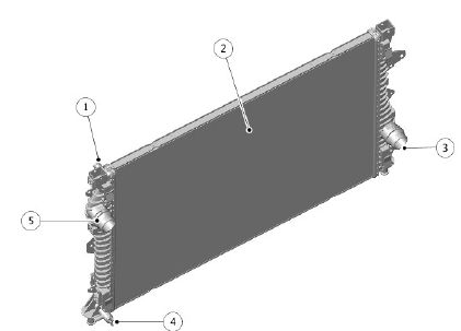
RADIATOR

- Overflow pipe connection
- Radiator
- Lower hose connection
- Charge air cooler fill connection
- Upper hose connection
The radiator is a vertical flow type with an aluminum core and plastic end tanks in the upper and lower position of the radiator. The radiator uses brazed aluminum tube technology to reduce weight. A low temperature zone is located at the left side of the radiator and provides cooled engine coolant for the ATF cooler.
The radiator is located in the vehicle by locating spigots and supports integrated into the end tanks. The supports are installed in rubber isolator bushes in the lower support bracket. The upper mounting of the end tanks is via a cross-strut attached to the vehicle body.
A drain plug is integrated into the bottom left end tank. Coolant outlet and inlet connections are incorporated into the left and right end tanks respectively. The right end tank also has a connection for coolant outlet to the ATF cooler and to the auxiliary radiator.
There is a connection to the charge air cooler to allow filling and bleeding of that system. The charge air cooler has a stand alone cooling circuit with its own radiator, pump and pipe work.
For additional information, refer to: Intake Air Distribution and Filtering (303-12B Intake Air Distribution and Filtering - INGENIUM I4 2.0L Diesel, Description and Operation).

