Land Rover Discovery: Electric Thermostat

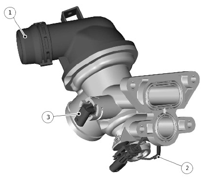
- Thermostat housing
- Heater element
- Temperature sensor
The electric thermostat independently controls the engine coolant flow to the cylinder head and cylinder block, improving engine warm-up times. The thermostat contains a wax expansion element. Inside the wax element is a heater element. When energised the heating element heats the wax element, partially controlling the thermostat function, along with engine coolant temperature control. Operation is therefore performed not only by the engine coolant temperature, but as specified by the ECM, enabling a finer control of the opening and closing of the thermostat. Opening of the thermostat is at a temperature of 95ºC +/- 2ºC (203ºF +/- 4ºF).
The electrically heated thermostat is used to regulate the engine coolant temperature by the ECM. The increased wax temperature provides higher engine coolant temperature during part load conditions and at low speed cycles. The increased engine coolant temperature results in reduced friction in the engine, improved combustion in the cylinders, and reduced fuel consumption and emissions. An electric thermostat heater element assembled within the wax element to regulate the engine coolant temperature during high load conditions and speed points to protect the engine from thermal overload.
Operation of the electric thermostat is controlled by the ECM upon the following inputs:
- Engine load
- Engine speed
- Vehicle speed
- Engine coolant temperature
- Intake air temperature
The electric thermostat has a battery feed from the EJB located in the right front of the engine compartment, a switched power supply from the ECM relay, located in the left EJB a hardwired connection to the ECM and a ground connection. If the ECM starts to regulate the system, the ECM supplies a ground path for the heater element in the electric thermostat.
This causes the element to expand and increase the opening dimension of the thermostat.
AUTOMATIC TRANSMISSION FLUID (ATF) COOLER

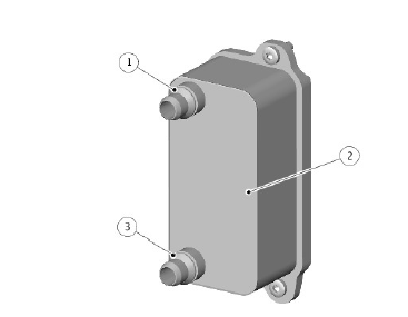
- Coolant inlet
- ATF cooler
- Coolant outlet
The ATF cooler is secured to the left side of the transmission main casing with three bolts. The ATF cooler has three lugs which locate in corresponding lugs on the transmission main casing and secured with a screw. The ATF cooler is an aluminum housing comprising louvred fins and plates. The plates allow a cross-flow of ATF and engine coolant through the ATF cooler.
The plates are immersed in engine coolant from the 'cold' side of the radiator which provides cooling of the ATF. The ATF cooler receives engine coolant from the low temperature zone at the end third of the radiator. The engine coolant flow through this section of the radiator is restricted by the ATF cooler. Therefore the engine coolant has a slower flow rate across the cooling tubes of this section of the radiator. This cools the engine coolant more than the main section of the radiator and consequently provides increased cooling of the ATF. The engine coolant then passes from the ATF cooler into the radiator bottom hose.
The ATF cooler has an integral thermostatic valve, which controls the ATF flow through the cooler. Flow is restricted to improve ATF warm-up time.
The thermostatic valve is closed at temperatures of 78ºC (172ºF) and below, starts to open at temperatures of between 78 and 84ºC (172 and 183ºF) and is fully open at temperatures of 96ºC (204ºF) and higher.
For additional information, refer to: Transmission Cooling (307-02 Transmission/Transaxle Cooling, Description and Operation).
FUEL COOLER

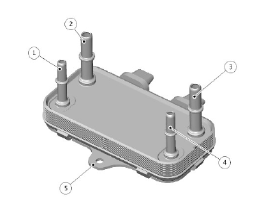
- Coolant outlet
- Fuel outlet
- Fuel inlet
- Coolant inlet
- Mounting bracket
The fuel cooler is located on left side of the engine, under the engine cover, mounted on a bracket.
The coolant inlet and outlet pipes are connected to the corresponding pipes of the charge air cooler circuit. The electric coolant pump circulates the coolant in this circuit.
For additional information, refer to: Intake Air Distribution and Filtering (303-12B Intake Air Distribution and Filtering - INGENIUM I4 2.0L Diesel, Description and Operation).
The fuel inlet connection is connected to the fuel rail and the outlet is connected to the fuel filter.
For additional information, refer to: Fuel Charging and Controls (303-04C Fuel Charging and Controls - INGENIUM I4 2.0L Diesel, Description and Operation).
ENGINE BLOCK HEATER
.jpg)
- 110 V Alternating Current (AC) version
- 240 V AC version
For vehicle markets subject to very cold climatic conditions, an engine block heater is installed in place of the cylinder block drain plug on the left side of the engine block. The engine block heater is either a 110 V AC or 240 V AC electric heater element (depending on the market), which can be connected to a domestic power supply via a connector in the left side grill of the front bumper.
OPERATION
When the thermostat is fully open, the by-pass circuit is closed and allows maximum engine coolant flow through the radiator system to provide maximum engine cooling. From the engine coolant outlet the majority of the engine coolant is passed through the radiator and the ATF cooler to the coolant pump, with a proportion still passing through the turbocharger, heater core and engine oil cooler.
When the thermostat is open the engine coolant flow from the radiator bottom hose passes through a venturi. This venturi creates a depression which pulls engine coolant through the ATF cooler. The upper section of the radiator provides low temperature cooling of the engine coolant for the ATF cooler.
The engine coolant expansion tank accommodates expansion of engine coolant due to temperature changes.
Electric Cooling Fan
The electric cooling fan is operated by a fan control module which is located at the rear of the cooling fan motor. The electric cooling fan control module regulates the voltage, and subsequently the speed, of the cooling fan motor in response to a PWM signal from the ECM. The ECM calculates the required fan speed from the engine temperature, Air Conditioning (A/C) system pressure and ATF temperature. Under hot operating conditions, the fan may continue to operate for up to five minutes after the engine has been switched off.
The speed of the cooling fan is also influenced by vehicle road speed. The ECM adjusts the speed of the cooling fan to compensate for the ram effect of vehicle speed, using the High Speed (HS) Controller Area Network (CAN) powertrain bus to receive the speed signal from the Anti-lock Brake System (ABS) control module.
INPUT/ OUTPUT DIAGRAM
.jpg)
A = HARDWIRED; AL = PULSE WIDTH MODULATION (PWM); AN = HIGH SPEED (HS) CONTROLLER AREA NETWORK (CAN) POWERTRAIN BUS
- Engine Control Module (ECM)
- Anti-lock Braking System (ABS) Control Module
- Cooling fan motor
- Electric thermostat
- Coolant pump
- Coolant pump - Charge air cooler cooling circuit
- Ground
- Power supply
- Electric thermostat - temperature sensor
- Coolant pump
- Engine Cooling Temperature (ECT) sensor

