Land Rover Discovery: Auxiliary Climate Control Fuel Fired Booster Heater - Operation
If a heating request is received and the ambient air temperature is less than or equal to 5ºC (41ºF), the Automatic Temperature Control Module (ATCM) transmits a 'supplemental heat' message to the Fuel Fired Booster Heater Control Module (FFBHCM) on the LIN bus. The control module responds by returning a 'supplemental heat' status message back to the ATCM. The control module will now initiate the Fuel Fired Booster Heater (FFBH) start sequence.
If the heating request is removed, or ambient air temperature rises to 8ºC (46ºF), the ATCM transmits a 'heater off' message to the FFBHCM on the LIN bus. Again, the FFBHCM responds by returning a 'heater off' status message back to the ATCM. The control module will now de-activate the FFBH.
If maximum heating is requested, ECM becomes the overriding factor. In this instance, the ATCM will change the LIN bus message from 'heater off' to 'supplemental heat' when engine coolant temperature measured by the FFBH is below or equal to 70ºC (158ºF). If the engine coolant temperature measured by the FFBH rises to 78ºC (172ºF) the ATCM returns the message to 'heater off'.
The FFBHCM will not start the FFBH, or will discontinue operation, if any of the following occur:
The FFBHCM is in the error lockout mode (see Diagnostics below)
The engine is not running, or stops running for approximately 4 seconds.
The time delay is included for stall detection
- 'fuel A cut-off' message is received from the CJB over the MS CAN Body and Comfort bus via the GWM.
For additional information, refer to: Electronic Engine Controls (303-14A Electronic Engine Controls - TD4 2.2L Diesel, Description and Operation).
A low fuel level message is received from the CJB over the MS CAN Comfort and Body bus via the GWM (see table below).
For additional information, refer to: Fuel Tank and Lines (310-01A Fuel Tank and Lines - TD4 2.2L Diesel, Description and Operation).
- If the supply voltage is above/below the required threshold.
The FFBHCM will control FFBH operation based on the following levels of fuel in the tank.
.jpg)
Start Sequence
At the beginning of a start sequence, the Fuel Fired Booster Heater Control Module (FFBHCM):
- energizes the glow pin and flame sensor to pre heat the combustion chamber,
- starts the combustion air fan at slow speed,
- and energizes the auxiliary coolant pump.
After approximately 30 seconds, the FFBHCM energizes the auxiliary fuel pump at the starting sequence speed. The fuel delivered by the auxiliary fuel pump evaporates in the combustion chamber, mixes with air from the combustion air fan and is ignited by the glow pin and flame sensor. The FFBHCM then progressively increases the speed of the auxiliary fuel pump and the combustion air fan. Once combustion is established the control module switches the glow pin and flame sensor to the flame sensing function to monitor combustion. From the beginning of the start sequence to stable combustion at full load takes approximately 150 seconds.
FULL AND PART LOAD COMBUSTION
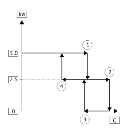
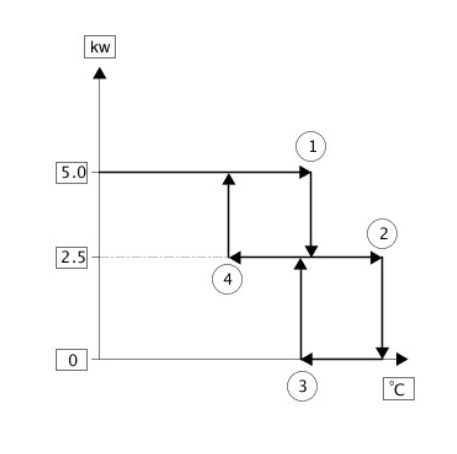
While the FFBH is running, the Fuel Fired Booster Heater Control Module (FFBHCM) cycles the heater between full load combustion, part load combustion (available for vehicles with Diesel engine) and a control idle phase of operation, depending on the temperature of the coolant in the FFBH heat exchanger.
The heat output level at part load combustion is 2.5kW. This rises to 5kW at full load combustion. The FFBHCM transmits the amount of fuel used by the FFBH to the Instrument Cluster (IC), and the FFBH coolant temperature to the ATCM.
Switching Point Temperatures
NOTE:
Vehicles with Diesel engine.

.jpg)
.jpg)
After the start sequence, the FFBHCM maintains full load combustion until the coolant temperature reaches switching point temperature 1. At this temperature, the FFBHCM decreases the speed of the auxiliary fuel pump and the combustion air fan to half speed, to produce part load combustion.
The FFBHCM maintains part load combustion while the coolant temperature remains between switching point temperatures 2 and 4. At part load combustion the temperature of the coolant will increase or decrease depending on the amount of heat required to heat the vehicle interior. If the coolant temperature decreases to switching point temperature 4, the FFBHCM increases the speed of the auxiliary fuel pump and the combustion air fan to full speed, to return to full load combustion. If the coolant temperature increases to switching point temperature 2, the FFBHCM enters a control idle phase of operation.
On entering the control idle phase, the FFBHCM immediately switches the auxiliary fuel pump off, to stop combustion, and starts a timer for the combustion air fan. After a 2 minute cool down period, the FFBHCM switches the combustion air fan off and then remains in the control idle phase while the coolant temperature remains above switching point temperature 3. If the coolant temperature decreases to switching point temperature 3, the FFBHCM initiates a start to part load combustion. A start to part load combustion takes approximately 90 seconds.
In order to limit the build-up of carbon deposits on the glow pin and flame sensor, the FFBHCM also enters the control idle phase if continuous combustion time exceeds 72 minutes (at part load, full load or a combination of both). After the cool down period, if the coolant is still in the temperature range that requires additional heat, the FFBHCM restarts the fuel fired booster heater.
SHUTDOWN
To stop the FFBH, the FFBHCM de-energizes the auxiliary fuel pump to stop combustion, but continues operation of the combustion air fan and the auxiliary coolant pump for a time, to cool down the FFBH. The cool down time is 100 seconds if the FFBH was operating at part load combustion and 175 seconds if the FFBH was operating at full load combustion.
DIAGNOSTICS
The Fuel Fired Booster Heater Control Module (FFBHCM) monitors the fuel fired booster heater system for faults. The Diagnostic Trouble Codes (DTC) are stored in a volatile memory in the FFBHCM, which can be interrogated by the Land Rover approved diagnostic system via the MS CAN Comfort bus.
The FFBHCM also incorporates an error lockout mode of operation that inhibits operation to prevent serious faults from causing further damage to the system. In the error lockout mode, the FFBHCM immediately stops the FFBH fuel pump, and stops the combustion air fan and auxiliary coolant pump after a cool down time of approximately 2 minutes. Error lockout occurs for:
- Start failure and flameout: If a start sequence fails to establish combustion, or a flameout occurs after combustion is established, the Fuel Fired Booster Heater Control Module (FFBHCM) immediately initiates another start sequence. The start failure or flameout is also recorded by an event timer in the FFBHCM. The event timer is increased by one after each start failure, flameout, and FFBH component failure, and will set back to zero if a subsequent start is successful. If the event timer increases to six (over any number of drive cycles), the FFBHCM enters the error lockout mode.
- Heat exchanger casing overheat: To protect the system from excessive temperatures, the Fuel Fired Booster Heater Control Module (FFBHCM) enters the error lockout mode if the heat exchanger coolant temperature exceeds 125ºC (257ºF).
The error lockout mode can be cleared using the Land Rover approved diagnostic system, or by disconnecting the battery power supply for a minimum of 10 seconds.
REMOTE OPERATION
The remote system includes the addition of a Fuel Fired Booster Heater (FFBH) receiver, FFBH antenna and a remote control for operation of the system. The FFBH unit remains as previously fitted. The IC message center displays FFBH messages when required.
The 868.3MHz RF signals transmitted by the remote control are received by the TV/FFBH antenna located in the rear left side window. The signals received by the antenna are detected by the FFBH receiver. A 'handshake' signal is sent back from the receiver to the remote control to confirm a valid on or off request and activate the remote control Light Emitting Diode (LED) accordingly. The receiver processes the signal it received and transmits the appropriate signals via a dedicated bus to the Fuel Fired Booster Heater Control Module (FFBHCM).
NOTE:
NOTE: The 'handshake' signal only confirms remote control-receiver communications were successful, and not that the FFBH has turned on.
When the FFBH is activated by the remote control, the FFBHCM will allow the FFBH to operate for 30 minutes or until an off request is received from the remote control or CJB. During the 30 minute period, the FFBH may operate in either full load combustion, part load combustion or a controlled idle phase of operation, depending on the temperature of the coolant in the heat exchanger.
PRE-BURN THRESHOLDS
The FFBH unit will only activate remotely if the following threshold conditions are met:
- Pre-burn battery voltage check: ≥11.5V (voltage at FFBH terminals)
- Pre-burn coolant temperature check: ≤15ºC (internal FFBH measurement)
- Pre-burn fuel level check: ≥7.5 liters (value stored in FFBH at ignition off)
The fuel level value stored within the FFBH unit is only updated when the engine is running. When starting the FFBH via remote control with the engine off, the fuel level value used in the FFBH calculations will be that stored at the last key off event. It is therefore possible for the FFBH to fail to operate remotely if the engine was stopped with a low fuel level; if the fuel tank is subsequently refueled, the FFBH stored fuel level will still read low if the engine has not been started since refueling.
If the FFBH does not activate due to low battery voltage or low fuel level, the Fuel Fired Booster Heater Control Module (FFBHCM) transmits a message on the LIN bus to the IC message center, which will display one of the following messages at ignition on:
- AUXILIARY HEATER UNAVAILABLE LOW FUEL
- AUXILIARY HEATER UNAVAILABLE LOW BATTERY
If both low fuel and low battery voltage messages are valid, the instrument cluster message center will alternate between the two messages.
REMOTE CONTROL 'PARK HEAT' TO ATCM 'SUPPLEMENTARY HEAT' TRANSITIONS
NOTE:
The FFBH can still be activated by the ATCM as previously described.
If the FFBH has been operated remotely ('park heat') and the vehicle is started whilst the FFBH is still active, it will transition into the ATCMcontrolled 'supplementary heat' mode if the ATCM requests it.
Should the ATCM then send a message to the FFBH to turn off, the FFBH will remain active if 30 minutes has not yet elapsed from the original remote control 'park heat' request. Once the remainder of 30 minutes has elapsed, the FFBH will turn off.
Switching Point Temperatures
NOTE: Vehicles with Diesel engine.
When remotely started the FFBH uses a different set of switching point temperatures to the normal 'supplemental heat' mode. This is because the remote start feature can start the FFBH with the engine off - thus different thresholds are required to optimize the heating of the engine coolant.
Switching Point Temperatures

.jpg)
.jpg)
Auxiliary climate control specifications
Torque Specifications
.jpg)

