Land Rover Discovery: Climate Control - Air Conditioning / Description
DESCRIPTION
The air conditioning system includes the following features:
- B-pillar mounted mid-level vents for row 2 passengers
- Face-level vents mounted in the C-pillar on vehicles with 5+2 seating, for row 3 passengers
- A mist sensor on the windscreen, used to detect conditions likely to cause misting
- An air quality sensor for detection of pollutant levels. When levels exceed set limits the system switches to re-circulation mode
- Timed climate control to pre-heat the cabin. This function can be activated remotely using the InControl Remote App
- ECO mode enables the system to adopt a more economical operating mode.
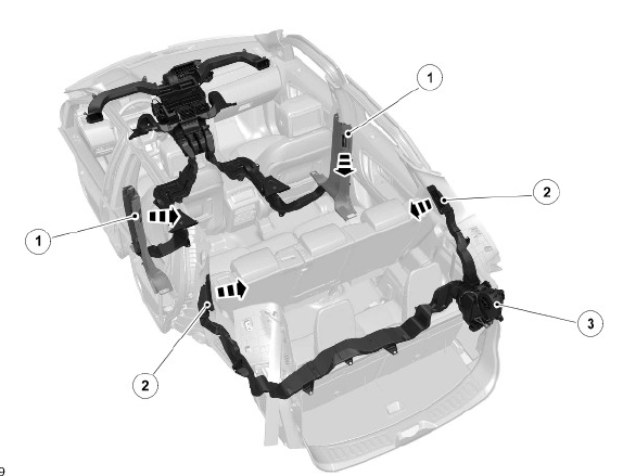
Air Conditioning Layout with Optional Auxiliary Rear Air Conditioning Unit

- B-pillar mounted mid-level vents for row two passengers
- Face-level vents mounted in the C-pillar on vehicles with 5+2 seating, for row three passengers
- Optional auxiliary air conditioning unit
The optional auxiliary air conditioning unit is discussed in another section.
For additional information, refer to: Auxiliary Climate Control (412-02 Auxiliary Climate Control, Description and Operation).
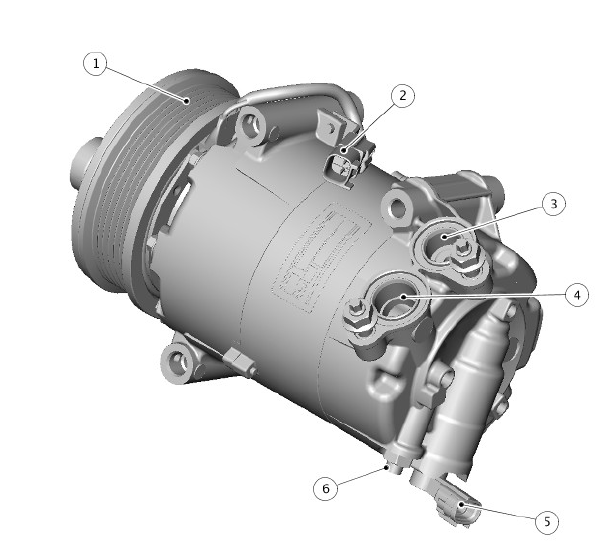
AIR CONDITIONING COMPRESSOR
2.0 GTDi Petrol
.gif)
- Pulley with electro-magnetic clutch
- Refrigerant inlet port
- Pressure relief valve
- Electronic control valve connector
- Refrigerant outlet port
- Electro-magnetic clutch connector.
TD4 2.2L Diesel

- Pulley with electro-magnetic clutch
- Electro-magnetic clutch connector
- Refrigerant outlet port
- Refrigerant inlet port
- Electronic control valve connector
- Pressure relief valve.
COMPRESSOR
The Air Conditioning (A/C) compressor is driven by the engine primary drive belt. The compressor circulates refrigerant around the A/C system by compressing low-pressure, low-temperature vapor from the evaporator and discharging the resultant high-pressure, high-temperature vapor to the condensor.
To protect the system from excessive pressure, a pressure relief valve is installed in the outlet side of the A/C compressor. The pressure relief valve vents excess pressure into the engine compartment.
Both compressors are variable displacement units. Displacement is controlled by an integral electronic control valve operated by the Automatic Temperature Control Module (ATCM). The control valve measures the input and output pressures of the refrigerant entering and leaving the compressor and controls the angle of the internal swash plate accordingly. The ATCM influences the control to match the thermal load of the evaporator and other factors.
Compressor clutch engagement is controlled by the ATCM.
For additional information, refer to: Control Components (412-01 Climate Control, Description and Operation).
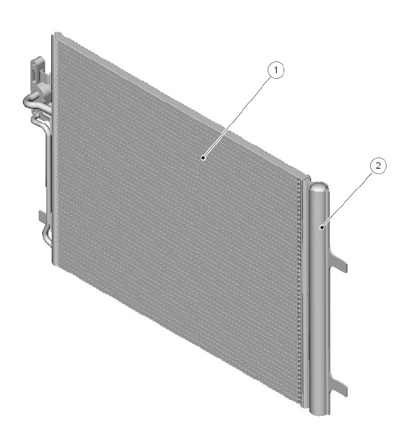
CONDENSOR

- Condensor
- Receiver/drier
The condensor transfers heat from the refrigerant to the surrounding air to cool the refrigerant and therefore convert the high-pressure vapor from the compressor into a liquid. The condensor is installed immediately in front of the radiator.
The condensor is classified as a sub-cooling condensor and consists of a fin and tube heat-exchanger core installed between 2 end tanks. Divisions in the end tanks separate the heat exchanger into a 4 pass upper (condensor) section and a 2 pass lower (sub-cooler) section.
The right end tank provides the connections to the high-pressure line from the A/C compressor and the liquid line to the evaporator.
RECEIVER/DRIER
The receiver/drier is integral with the condensor left end-tank and removes solid impurities and moisture from the refrigerant. It also acts as a reservoir for liquid refrigerant to accommodate changes of heat load at the evaporator.
Refrigerant entering the receiver drier passes through a filter and a desiccant pack, then collects in the base of the unit before flowing through the outlet pipe back to the condensor.
REFRIGERANT PRESSURE SENSOR
.jpg)
The refrigerant pressure sensor provides the Automatic Temperature Control Module (ATCM) with a pressure input from the high-pressure side of the refrigerant system. The refrigerant pressure sensor is hardwired to the ATCM, which uses the signal to control operation of the A/C compressor through the A/C compressor clutch relay in the Battery Junction Box (BJB).
Additionally, the ATCM is able to increase the amount of re-circulated air, if it is required. The ATCM broadcasts the refrigerant high-pressure value over the medium-speed Controller Area Network (CAN) comfort bus to the Engine Control Module (ECM) via the Gateway Module (GWM). The ECM calculates the additional load on the engine when the A/C compressor is working. For example, this signal is used as an input, for the idle speed control.
The refrigerant pressure sensor is located in the refrigerant line between the condensor and the Thermostatic Expansion Valve (TXV).
THERMOSTATIC EXPANSION VALVE
.jpg)
- Metering valve
- Housing
- Diaphragm
- Temperature sensor
- Outlet passage from evaporator
- Inlet passage to evaporator.
The Thermostatic Expansion Valve (TXV) meters the flow of refrigerant into the evaporator to match the refrigerant flow with the heat-load of the air passing through the evaporator.
The TXV is a block type valve located behind the climate control assembly, and attached to the inlet and outlet ports of the evaporator. The TXV consists of an aluminum housing containing inlet and outlet passages. A ball and spring metering valve is installed in the inlet passage and a temperature sensor is installed in the outlet passage. The temperature sensor consists of a temperature sensitive tube connected to a diaphragm. The bottom end of the temperature sensitive tube acts on the ball of the metering valve.
Pressure on top of the diaphragm is controlled by the evaporator outlettemperature conducted through the temperature sensitive tube. The bottom of the diaphragm senses evaporator outlet pressure.
Liquid refrigerant flows through the metering valve into the evaporator. The restriction across the metering valve reduces the pressure and temperature of the refrigerant. The restriction also changes the liquid stream of refrigerant into a fine spray, to improve the evaporation process. As the refrigerant passes through the evaporator, it absorbs heat from the air flowing through the evaporator. The increase in temperature causes the refrigerant to vaporize and increase in pressure.
The temperature and pressure of the refrigerant leaving the evaporator acts on the diaphragm and temperature sensitive tube, which regulate the metering valve opening and so controls the volume of refrigerant flowing through the evaporator. The warmer the air flowing through the evaporator, the more heat available to evaporate refrigerant and thus the greater volume of refrigerant allowed through the metering valve.
EVAPORATOR
.jpg)
- Heater core
- Evaporator.
The evaporator is installed in the climate control assembly, between the blower and the heater core, to absorb heat from the exterior or recirculated air. Low pressure, low temperature refrigerant changes from liquid to vapor in the evaporator, absorbing large quantities of heat as it changes state.
Most of the moisture in the air passing through the evaporator condenses into water, which drains out of the vehicle by passing through a drain tube to the underside of the vehicle.
REFRIGERANT LINES
To maintain similar flow velocities around the A/C system the diameter of the refrigerant lines varies to suit the two pressure/temperature regimes.
Larger diameter pipes are installed in the low pressure/temperature regime and smaller diameter pipes are installed in the high pressure/temperature regime.
Nylon lined, low permeability rubber hoses are used in the low pressure line into the A/C compressor, and in the high pressure line from the condensor.
The remainder of the refrigerant lines are manufactured from aluminum.
Low and high pressure charging connections are incorporated into the refrigerant lines for system servicing.
INTERNAL HEAT EXCHANGER
.jpg)
- High pressure line
- Low pressure line
- Internal Heat Exchanger (IHX)
The Internal Heat Exchanger (IHX) is incorporated within the air conditioning pipes.
The IHX is part of the vehicle's air conditioning system and helps to increase its cooling capacity. The IHX combines a section of the system's pipework before and after the evaporator into one pipe. It uses the cold vapour exiting the evaporator to cool the hot liquid before it enters the expansion device, resulting in increased cooling. It also uses the heat to increase the temperature of the low temperature gas before it enters the compressor.
The amount of energy used by the air conditioning system can be reduced by taking advantage of this increased cooling.
This gives the following benefits:
- Helps reduce tailpipe CO2 emissions, due to less engine load
- Improved fuel economy, due to reduced compressor power requirements
- R1234yf - Increases the system capacity to increase cooling.

