Land Rover Discovery: TAS Graphics
Land Rover Discovery (2009–2016) Service Manual / General Information / About This Manual / TAS Graphics
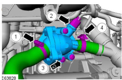
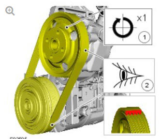
Colors used in the graphic are as follows:
- Blue - Indicates the target item, item to be removed/installed or disassembled/assembled
- Green and Brown - Indicates a secondary item that needs to be detached, removed/installed or disassembled/assembled prior to the target item
- Yellow - Component that is touched or affected in a way but remains in the vehicle. It may be detached, attached, moved, modified, checked, adjusted etc.
- Magenta - Indicates electrical connectors and fasteners such as nuts, bolts, clamps or clips
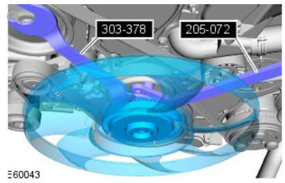
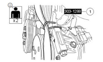
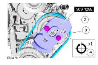
- Pale Blue - is for the special tool(s) and general equipment.
There may be multiple steps assigned to one illustration.
Numbered pointers are used to indicate the number of electrical connectors and fasteners such as nuts, bolts, clamps or clips.
Items in the illustration can be transparent or use cutouts to show hidden detail(s).
READ NEXT:
 TAS Symbols
Symbols are used inside the graphics and in the text area to enhance the
information display. The following paragraphs describe the various types
and categories of symbols.
Prohibition symbols advise
Diesel Fuel System Health and Safety Precautions
DESCRIPTION AND OPERATION
WARNINGS:
Fuel may not give adequate warning before toxic or harmful
effects
arise.
Exposure to fuel can be harmful and can cause severe health
damage or death.
Prov
General Service Information
INTRODUCTION
This manual has been written in a format that is designed to meet the needs
of Land Rover technicians worldwide and to assist them in the efficient
repair and maintenance of Land Rover ve
SEE MORE:
Starting System - Ingenium
i4 2.0l Diesel / Description
and Operation
COMPONENT LOCATION - SHEET 1 OF 3 - VEHICLES
WITHOUT AUTO STOP/ START SYSTEM
Stop/Start switch
Engine Control Module (ECM)
Starter motor
COMPONENT LOCATION - SHEET 2 OF 3 - VEHICLES WITH AUTO STOP/START SYSTEM - MANUAL TRANSMISSION
Stop/Start switch
Engine Control Module (ECM)
Starter
Oil Cooler
Engine coolant outlet
Engine coolant inlet from cylinder block
Oil pressure outlet to cylinder block
Oil pressure inlet / Anti-drain valve
The engine oil cooler is located on the side of the cylinder block, below the
turbocharger and exhaust manifold. The oil cooler is sealed to the cylinder
© 2019-2025 Copyright www.lrdisc.com
