Land Rover Discovery: Stop / Start Switch
.gif)
The stop/start switch is located in the Instrument Panel (IP) and is hardwired to the Central Junction Box (CJB). When the switch is pressed two signal lines from the CJB are connected to ground.
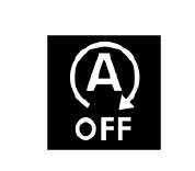
AUTO STOP/START WARNING INDICATOR

The auto stop/start warning indicator is located in the Instrument Cluster (IC). The warning indicator comes on when the engine stops during a stop/start cycle, then goes off when the engine restarts. The warning indicator is controlled in the IC by a Medium Speed Controller Area Network (MS-CAN) comfort bus message from the ECM.
AUTO STOP/START SWITCH
.jpg)
The auto stop/start switch is located in the front floor console. An amber Light Emitting Diode (LED) in the auto stop/start switch remains illuminated while the auto stop/start system is active. The auto stop/start switch sends a signal to the CJB using the MS-CAN comfort bus, to inform the ECM assembly when on or off.
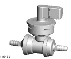
BRAKE VACUUM SWITCH

To ensure the brake system is never compromised, a brake vacuum switch is installed on auto stop/start vehicles to monitor vacuum reserves in the brake booster. The brake vacuum switch is mounted in the vacuum pipe and hardwired to the ECM. If the brake vacuum decreases below a set threshold while stop/start is enabled, the ECM either:
- Restarts the engine to replenish the vacuum reserves
- Inhibits the engine shutting down if vacuum reserves are not sufficient.
An example of vacuum reserves depleting, is by the driver repeatedly pressing the brake pedal while the engine is shut down during an auto stop/start stop. This action will initiate an engine restart when vacuum reserves decrease below the set threshold.
If a fault develops with the brake vacuum sensor a Diagnostic Trouble Code (DTC) will be logged in the ECM.
NEUTRAL GEAR SENSOR
.jpg)
A permanent magnet, linear contactless displacement sensor is located on the exterior of the transmission casing and hardwired to the ECM. The sensors function is to detect that neutral gear has been selected within a calibrated window.
SYSTEM OPERATION

