Land Rover Discovery: Side Panel Sheet Metal Repairs Side Panel (G1770901) - Installation
Land Rover Discovery (2009–2016) Service Manual / Body / Body Repairs and General
Information / Side Panel Sheet
Metal Repairs
Side Panel (G1770901) / Side Panel Sheet
Metal Repairs
Side Panel (G1770901)
- Installation
Installation
NOTE:
Make sure that a zinc rich primer is applied to any bare metal surfaces.
- Dress the flanges where necessary
- Clean and prepare the panel surfaces.
CAUTION:
This step requires the aid of another technician as the side panel is heavy.
- Offer up the new side panel and clamp into position. Check alignment, if correct, proceed to next step, if not, rectify and recheck before proceeding.
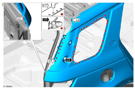
NOTE:
Follow steps 1 and 2 as shown to cut the MIG braze slots.
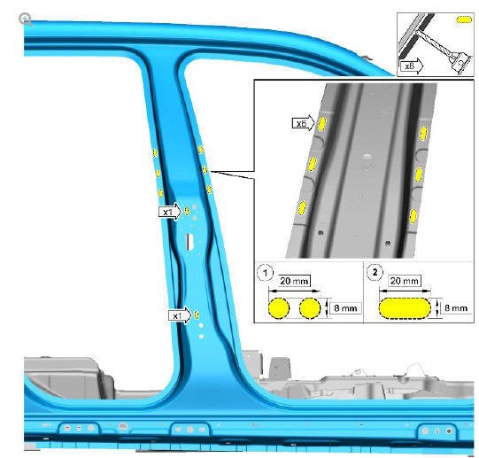
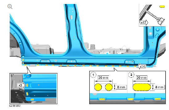
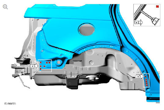
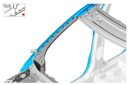
- Mark the position and cut slots in the new side panel where the Metal Inert Gas (MIG) braze slot welds are to be installed as indicated.
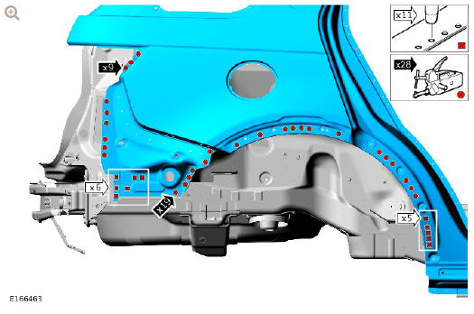
NOTE:
Follow steps 1 and 2 as shown to cut the MIG braze slots.
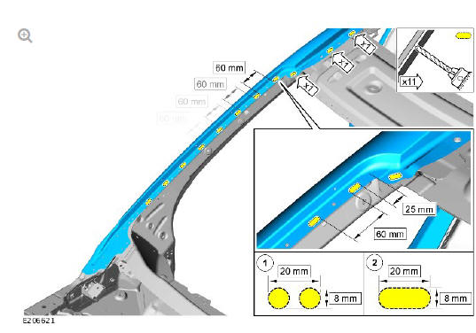
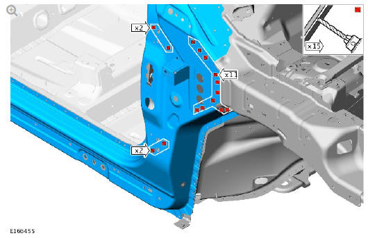
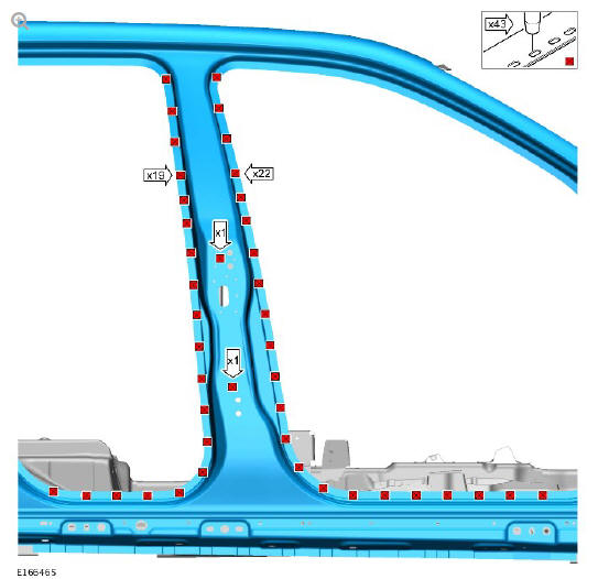
- Mark the position and cut slots in the new side panel where the MIG braze slot welds are to be installed as indicated.
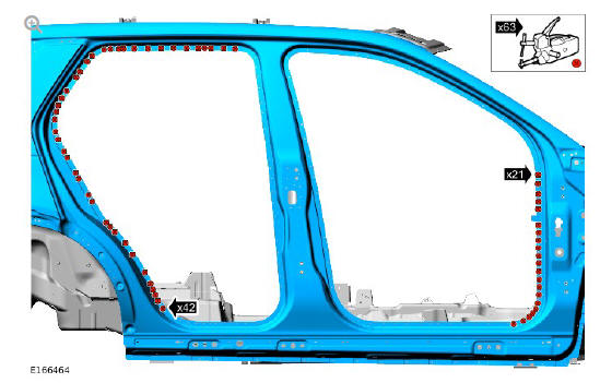
NOTE:
Follow steps 1 to 3 as shown to cut the MIG braze slots.
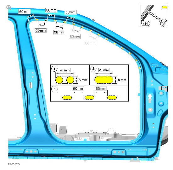
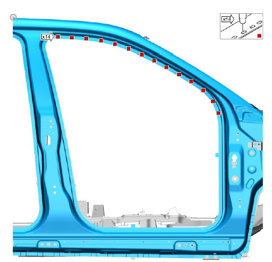
- Mark the position and cut slots in the new side panel where the MIG braze slot welds are to be installed as indicated.
NOTE:
Follow steps 1 to 3 as shown to cut the MIG braze slots.
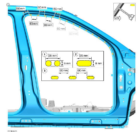
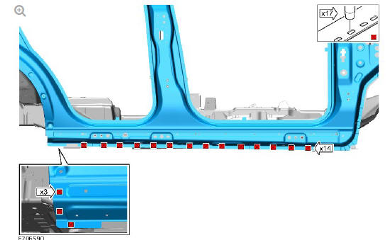
- Mark the position and cut slots in the new side panel where the MIG braze slot welds are to be installed as indicated.
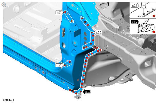
NOTE:
Follow steps 1 and 2 as shown to cut the MIG braze slots.
- Mark the position and cut slots in the new side panel where the MIG braze slot welds are to be installed as indicated.
NOTE:
Follow steps 1 and 2 as shown to cut the MIG braze slots.
- Mark the position and cut slots in the new side panel where the MIG braze slot welds are to be installed as indicated.
- Drill holes in the new side panel where the MIG plug welds are to be installed as indicated.
- Drill holes in the new side panel where the MIG plug welds are to be installed as indicated.
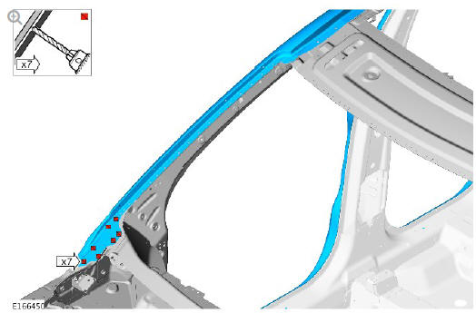
- Drill holes in the new side panel where the MIG plug welds are to be installed as indicated.
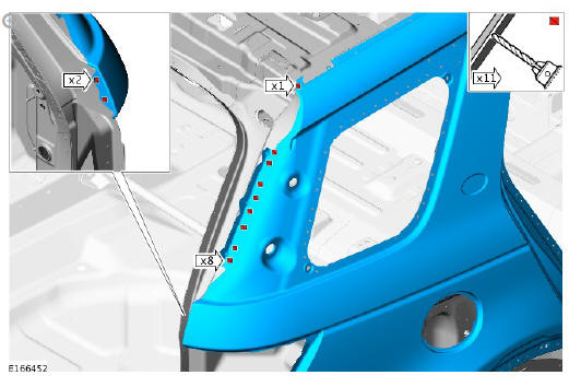
- Drill holes in the new side panel where the MIG plug welds are to be installed as indicated.
CAUTION:
This step requires the aid of another technician as the side panel is heavy.
- Remove the side panel.
- Deburr the drilled slots and holes.
- Clean and prepare the panel surfaces.
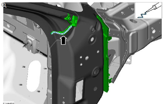
- Apply a 5 mm bead of Land Rover recommended sealer to the Noise, Vibration and Harshness (NVH) components as indicated.
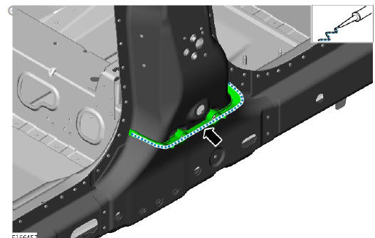
- Apply a 5 mm bead of Land Rover recommended sealer to the NVH components as indicated.
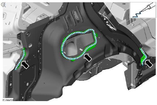
- Apply a 5 mm bead of Land Rover recommended sealer to the NVH components as indicated.
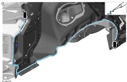
- Apply a 5 mm bead of Land Rover recommended sealer to the vehicle assembly as indicated.
CAUTION:
This step requires the aid of another technician as the side panel is heavy.
- Offer up the new side panel and clamp into position. Check alignment, if correct, proceed to next step, if not, rectify and recheck before proceeding.
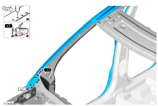
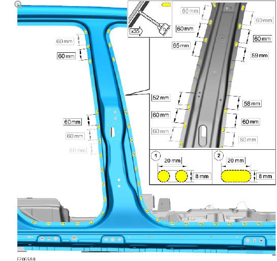
- Install the spot and MIG plug welds as indicated.
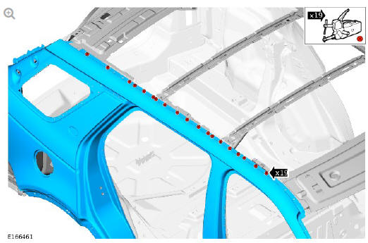
- Install the spot welds as indicated.
- Install the spot and MIG plug welds as indicated.
- Install the spot and MIG plug welds as indicated.
- Install the spot welds as indicated.
- Install the spot and MIG plug welds as indicated.
- Install the MIG braze slot welds as indicated.
- Install the MIG braze slot welds as indicated.
- Install the MIG braze slot welds as indicated.
- Install the MIG braze slot welds as indicated.
- Dress all welded joints.
- Apply a Land Rover recommended sealer and seal the panel flange edges of the MIG braze slot welds in the door aperture areas to prevent water ingress.
- Make sure that any open or exposed panel joints are correctly sealed.
- Make sure corrosion protection is applied to all areas affected by repair.
- The installation of associated panels and components is the reversal of removal procedure.
READ NEXT:
 Side Panel Sheet
Metal Repairs
Rocker Panel and 'B'
Pillar Outer
Panel (G1770927) -
Removal
Side Panel Sheet
Metal Repairs
Rocker Panel and 'B'
Pillar Outer
Panel (G1770927) -
Removal
NOTE:
The rocker panel and B-pillar outer is installed in conjunction with:
Front bumper cover
Front fender
Front fender splash shield
Front door
Rear door
Front seat
Rear seat cushion
Cowl s
Side Panel Sheet
Metal Repairs
Rocker Panel and 'B'
Pillar Outer
Panel (G1770927) -
Installation
Installation
Dress the flanges where necessary.
Using the old rocker panel and B-pillar outer for reference measure,
mark and cut the new rocker panel and B-pillar outer where the
Metal Inert Gas
SEE MORE:
Planetary Gear Trains
Gear set 1
Gearset 2
Gear set 3
Gear set 4
The planetary gear trains used on the 9HP48 transmission comprise four
planetary gear sets; GS1, GS2, GS3 and GS4.
Engine torque is transferred, via operation of single or combinations of
multiplate clutches, multiplate brakes and two dog clutches,
Anti-theft - Active / Operation
Operation
The Central Junction Box (CJB) automatically arms and disarms the active
anti-theft system when it operates the Central Locking System (CLS).
On vehicles without a volumetric sensor, only the perimeter mode is
available to monitor the hinged panels and the validity of the smart key.
When
© 2019-2025 Copyright www.lrdisc.com
