Land Rover Discovery: Rear View Mirrors - Description
Description
REAR VIEW MIRROR
Rear view mirrors consist of mirror glass in a housing that is connected to a mounting stem by a ball joint. The mounting stem is attached to a pad bonded onto the windshield and concealed by two covers.
Manual Dimming Rear View Mirror
.92.jpg)
- Upper cover
- Mounting stem
- Lever
- Lower cover
Manual dimming is performed with a lever on the underside of the mirror body.
Automatic Dimming Rear View Mirror
.93.jpg)
- Upper cover
- Rear light sensor
- Front light sensor
- Lower cover
- Auto High Beam Control Module (AHBCM) and camera (if fitted)
- Electrical connector
- Universal transmitter status indicator
- Universal transmitter channel buttons
Automatic dimming is performed by electrochromic mirror glass that automatically dims to reduce glare from the headlights of following vehicles in dark or low light conditions.
Light sensors on the front and rear of the interior mirror provide light level inputs for the automatic dimming function.
Automatic dimming rear view mirrors are connected to the vehicle wiring by an electrical connector concealed by covers installed over the mounting stem. On vehicles with the automatic high beam function, the covers also contain the IPCM.
For additional information, refer to: Exterior Lighting (417-01 Exterior Lighting, Description and Operation).
Rear view mirrors which incorporate a HomeLink universal transmitter have operating buttons on the lower face. They also have a red Light Emitting Diode (LED) (amber LED on North American Specification (NAS) market) status indicator, next to the buttons, which illuminates when the universal transmitter is transmitting.
The universal transmitter can operate up to three home or office remotely operated systems (e.g. garage door/gate openers, lighting and security systems), replacing the individual hand held transmitters required for each system. Universal transmitter operating frequencies vary across markets.
Power for the feature(s) in the automatic dimming interior mirror is provided by an ignition feed from the RJB.
DOOR MIRRORS
.94.jpg)
- Door mirror motor assembly
- Door mirror glass heating element connectors
- Mounting screws
- Door mirror body assembly
- Door mirror electrical connector
- Proximity camera electrical connector (where fitted)
- Ambient Air Temperature sensor (AAT)
- Approach lamp
- Wade sensor (where fitted)Proximity camera (where fitted)
- Proximity camera (where fitted)
- Side repeater lamp
- Door mirror cover
- Door mirror glass
The door mirrors are attached to the front door structure and connected to the door harness.
The door mirrors fold forwards or rearwards on impact. On vehicles without the mirror foldback option, the mirrors can be folded into a park position by pushing the mirror housing towards the side window.
Exterior mirror heating is provided by heater elements bonded to the back of the door mirror glass. The power supply to the heater elements is controlled by the respective door modules, in response to signals from the CJB.
Door mirrors with the foldback feature incorporate a foldback motor in the hinge. Operation of the foldback motor is controlled by the respective door modules in response to signals from the driver door switchpack
DOOR MIRROR MOTOR ASSEMBLY

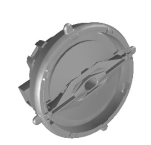
The door mirror glasses each incorporate the door mirror motor assembly which contains two adjustment motors for the door mirror glass. One for horizontal (left/right) adjustment and one for vertical (up/down) adjustment.
Power to the motors is controlled by the respective door modules in response to signals from the driver door switchpack. On vehicles with memory recall, the door mirror motor assemblies incorporate horizontal and vertical plane position sensors.
DOOR MIRROR SWITCHES
.96.jpg)
Left and right select switches and an adjustment switch for the door mirrors are incorporated into the driver door switchpack in the door casing.
FRONT DOOR MODULES

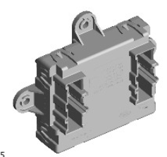
Each front door module is attached to the closing panel in the related door and connected to the door harness.
The two front door modules interpret the signals from the CJB and the driver door switchpack into appropriate outputs for the related door mirrors. For operation of the various door mirror functions each door module is powered by a permanent battery feed from the CJB. The live feed to the mirror foldback motors goes off 5 minutes after the ignition is switched off.

