Land Rover Discovery: Hydraulic Brake Actuation / Description and Operation
COMPONENT LOCATION
NOTE:
Right Hand Drive (RHD) illustration shown, Left Hand Drive (LHD) illustration similar.
.jpg)
- Brake pedal
- Hydraulic pipes
- Integrated Hydraulic Control Unit (HCU) and Anti-lock Brake System (ABS) module
- Brake master cylinder and fluid reservoir.
OVERVIEW
The hydraulic brake system is a diagonally split, dual circuit system and consists of the brake pedal, brake master cylinder, fluid reservoir, Hydraulic Control Unit (HCU) and the brake pipes and hoses.
The preformed rigid brake pipes distribute pressure from the master cylinder to flexible hoses connected to the front and rear calipers, via the integrated HCU and Anti-lock Brake System (ABS) control module.
DESCRIPTION
BRAKE PEDAL

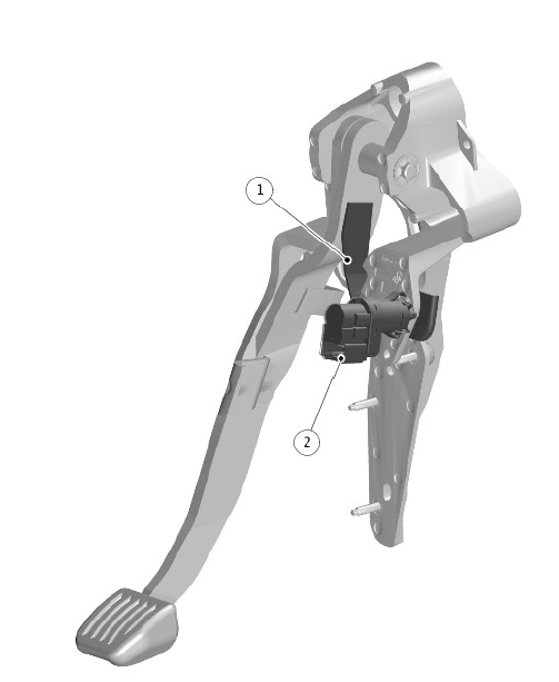
- Brake pedal switch operating plate
- Brake pedal switch
The brake pedal is mounted in a bracket attached to the rear side of the engine bulkhead. The brake pedal is connected to the brake booster push rod with a clevis pin.
The brake pedal switch is mounted on the brake pedal bracket and operated by a plate attached to the brake pedal. The brake pedal switch is a combined switch, contains a stop lamp switch and a brake test switch in one housing. Both switches are connected hardwired to the Central Junction Box (CJB), to give independent signals of brake pedal operation.

