Land Rover Discovery: Headlamp Washers - Operation
When the engine is running (power mode 7) and the CJB has received a headlamps 'ON' LIN bus message from the lighting control switch, when the driver operates the wipers and washers control switch in the windshield wash position, the CJB will initiate the headlamp washer sequence.
The CJB then suspends headlamp wash activation for the next 10 minutes and 3 operations of the wash/wipe switch, with the headlamp power washers activated on the fourth operation of the switch and after the 10 minute period has expired.
The number of headlamp washer operations in given period is limited to preserve the washer fluid in the washer reservoir. The headlamp washers are activated on the first operation of the windshield washer with the headlamp on. The CJB then suspends headlamp washer activation for the next three operations of the wipers and washers control switch in the windshield washer position, with the headlamp power washers activated again on the fourth operation of the switch and completion of a 10 minute timer.
The timer and event counter is cleared following an ignition cycle or moving the lighting control switch to 'OFF' then back to 'ON'.
When the driver moves the wipers and washers control switch to the windshield wash position and the headlamps are 'ON', the CJB provides a ground for the two headlamp washer relays in the BJB. One relay contacts close and power is supplied to the headlamp washer pump. The other headlamp washer relay contacts open and provide a ground path for the headlamp washer pump. Each relay is energized for a period which is dependent on ambient temperature, which powers the headlamp washer pump to operate the left headlamp washer, the CJB then reverses the sequence to power the headlamp washer pump in the opposite direction to operate the headlamp washer pump to operate the right headlamp washer.
If the washer fluid level becomes low, the CJB suspends headlamp washer operation to preserve the remaining washer fluid.
WASHER FLUID LEVEL SENSOR
The washer fluid level sensor is a basic float switch located within the windshield washer reservoir. the switch is connected to the CJB. When the fluid level is the reservoir falls, the level sensor switch is operated, completing a ground path to the CJB.
The CJB will send a CAN message to the instrument cluster to illuminate the windshield washer reservoir low warning indicator and display a message in the message center.
CONTROL DIAGRAM
NOTE:
A = Hardwired; AP = medium speed CAN comfort systems; O = LIN bus
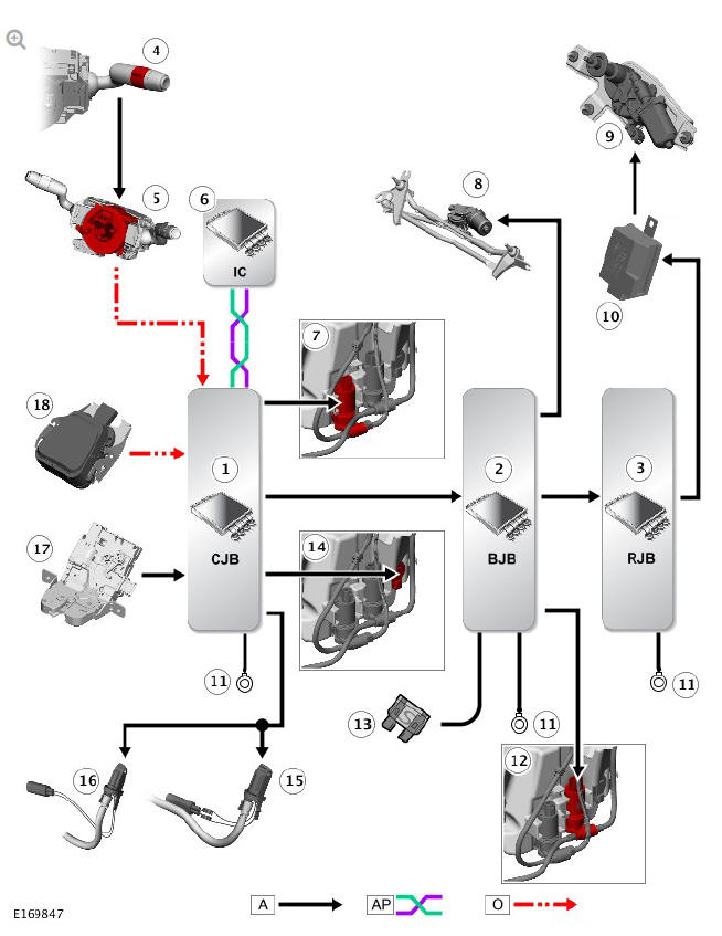
- Central Junction Box (CJB)
- Battery Junction Box (BJB)
- Rear Junction Box (RJB)
- Right steering column multifunction switch - wipers and washers control switch
- Clockspring
- Instrument Cluster (IC)
- Front/rear washer pump
- Windshield wiper motor
- Rear wiper motor
- RF filter - rear wiper motor
- Ground
- Headlamp washer pump
- Power supply
- Washer fluid level sensor
- Right heated washer jet
- Left heated washer jet
- Tailgate latch
- Rain/light sensor
READ NEXT:
 Wipers and Washers / Diagnosis and Testing
PRINCIPLES OF OPERATION
For a detailed description of the Wipers and Washers system, refer to the
relevant Description and Operation section in the workshop manual. REFER
to: Wipers and Washers (501-1
SEE MORE:
Resuming the speed and follow mode
RES should only be used if the
driver is aware of the set speed and
intends to return to it.
By pressing the RES button after ACC has
been cancelled (e.g. after braking), ACC
will become active again provided that
the set speed memory has not been
erased. The original set speed will be
resumed (unle
Radio frequency transceiver
In some countries, the Radio Frequency
(RF) transceiver is also known as the
HomeLink Universal Transceiver.
The RF transceiver is located in the
rear-view mirror. It can be programmed
to transmit the signals of up to 3 different
hand-held transmitters. These can be used
to operate garage doors, en
