Land Rover Discovery: Engine System - General Information Leakage Test Using Smoke Test Equipment (G1445299) / General Procedures
CAUTION:
The compressed air line supply pressure must be between 3.5 and 12 bar (50 and 175 psi) for the smoke test equipment to function correctly. Do not exceed this pressure. Failure to follow this instruction may result in damage to the smoke test equipment.
NOTES:
- The vehicle battery must be in good condition and fully charged before carrying out this procedure.
- On vehicles with 3.0L TDV6, it will be necessary to insert smoke at both air cleaner outlet pipes independently if the right hand turbocharger and associated hoses are to be tested.
- In some cases it may be necessary to remove undertrays, trim or engine covers to obtain access to all potential leak locations.
- Some variation in the illustrations may occur, but the essential information is always correct.
- For further information regarding operation of the test equipment refer to the manufacturers operators manual supplied with the kit.
WARNING:
Use an additional support to prevent the hood from falling if the smoke test equipment is secured to the hood. Failure to follow this instruction may result in personal injury.
.jpg)
Install the smoke test equipment to a suitable location under the hood.
Connect a suitable compressed air line to the smoke test equipment.
Connect the smoke test equipment positive power cable to the battery positive terminal.
WARNING:
Do not connect the smoke test equipment negative cable to the battery negative terminal.
Connect the smoke test equipment negative cable to a suitable body ground point.
NOTE:
A flashing green light indicates low battery voltage. In this case, place the battery on charge and make sure that the battery is fully charged before using the smoke test equipment.
.jpg)
Observe the power indicator lamp on the smoke test equipment.
Make sure that a continuous green light is displayed.
NOTES:
- In some cases it may be necessary to remove the air cleaner(s) to allow access to the air cleaner outlet pipes.
- In some cases it will be necessary to cap one of the air cleaner outlet pipes. Use the blanking caps supplied in the kit to cap the open orifice.
.jpg)
Disconnect the air cleaner outlet pipe(s).
NOTE:
Make sure the smoke test equipment adapter is a good fit to the air cleaner outlet pipe. This must be an air tight seal.
.jpg)
Connect the smoke test equipment supply hose to the air cleaner outlet pipe.
- Install the appropriate adapter to the air cleaner outlet pipe.
- Connect the smoke test equipment supply hose to the adapter link hose.
NOTES:
- The flow control valve must be in the fully open position.
- Smoke is produced for 5 minutes. The smoke test equipment will automatically switch off after this period of time.
.jpg)
Switch the smoke test equipment on.
Remove the oil filler cap, and observe until a constant flow of smoke is visible leaving the oil filler orifice. Install the oil filler cap
NOTE:
The longer smoke is allowed to exit from a leak, the more fluorescent dye will be deposited at a leak location.
Using the torch supplied in the kit set to white light, look for escaping smoke. Alternatively, use the ultraviolet light to look for fluorescent dye deposits at the source of a leak.
Engine System - General Information Piston Inspection (G61244) General Procedures
CAUTION:
Do not use any aggressive cleaning fluid or a wire brush to clean the piston.

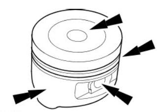
Carry out a visual inspection.
- Clean the piston skirt, pin bush, ring grooves and crown and check for wear or cracks.
- If there are signs of wear on the piston skirt, check whether the connecting rod is twisted or bent.
Engine System - General Information Piston Pin Diameter (G61250) General Procedures
NOTE:
The piston and piston pin are a matched pair. Do not mix up the components.
.jpg)
Measure the piston pin diameter.
- Measure the diameter in two directions.
- If the values are not to specification, install a new piston and a new piston pin.
Engine System - General Information Piston Pin to Bore Diameter (G61245) General Procedures
GENERAL PROCEDURES
NOTE:
The piston and piston pin form a matched pair. Do not mix up the components.
.jpg)
Measure the diameter of the piston pin bore.
- Measure the diameter in two directions.
- If the values are not to specification, install both a new piston and a new piston pin.
Engine System - General Information Piston Ring end Gap (G61248)
General Procedures
CAUTION:
Do not mix up the piston rings. Install the piston rings in the same position and location.
.jpg)
Using the Feeler Gauge, measure the piston ring gap.
- The values given in the specification refer to a gauge ring used during production.
Engine System - General Information Piston Ring-to-groove Clearance (G61249)
General Procedures
NOTE:
The piston ring must protrude from the piston groove. To determine the piston ring clearance, insert the Feeler Gauge right to the back of the groove, behind the wear ridge.
.jpg)
Using the Feeler Gauge, measure the piston ring clearance.
Engine System - General Information Valve Spring Free Length (G61254) General Procedures
.jpg)
Using a vernier gauge, measure the free length of each valve spring. Verify the length is within specification.
Engine System - General Information Valve Stem Diameter (G61253)
General Procedures
.jpg)
Using a micrometer measure the diameter of the valve stems.
- If the measurements are not to specification, install a new valve.

