Land Rover Discovery: Diagnosis and Testing Navigation System / Symptom chart
.jpg)
.jpg)
.jpg)
.jpg)
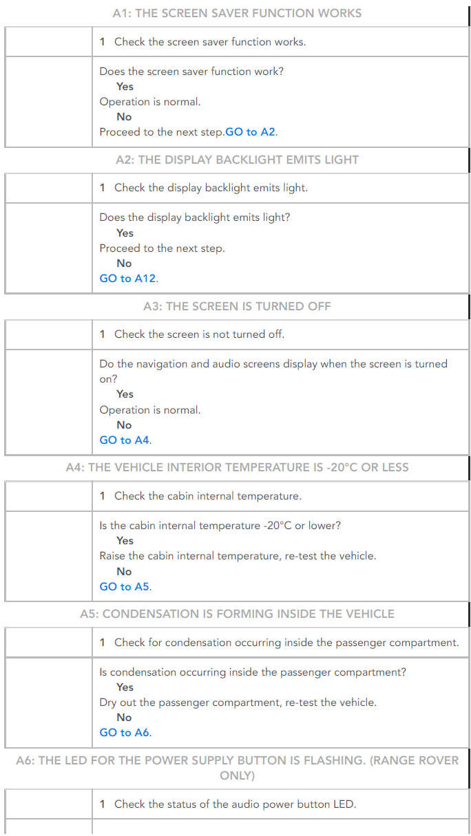
SYMPTOM:
Black screen (navigation and audio screens do not display)
POSSIBLE CAUSE:
- Temperature in passenger compartment too low
- Condensation in passenger compartment
- Electrical harness open/short circuit, disconnected
- Component failure
ACTION:
- GO to Pinpoint Test A.
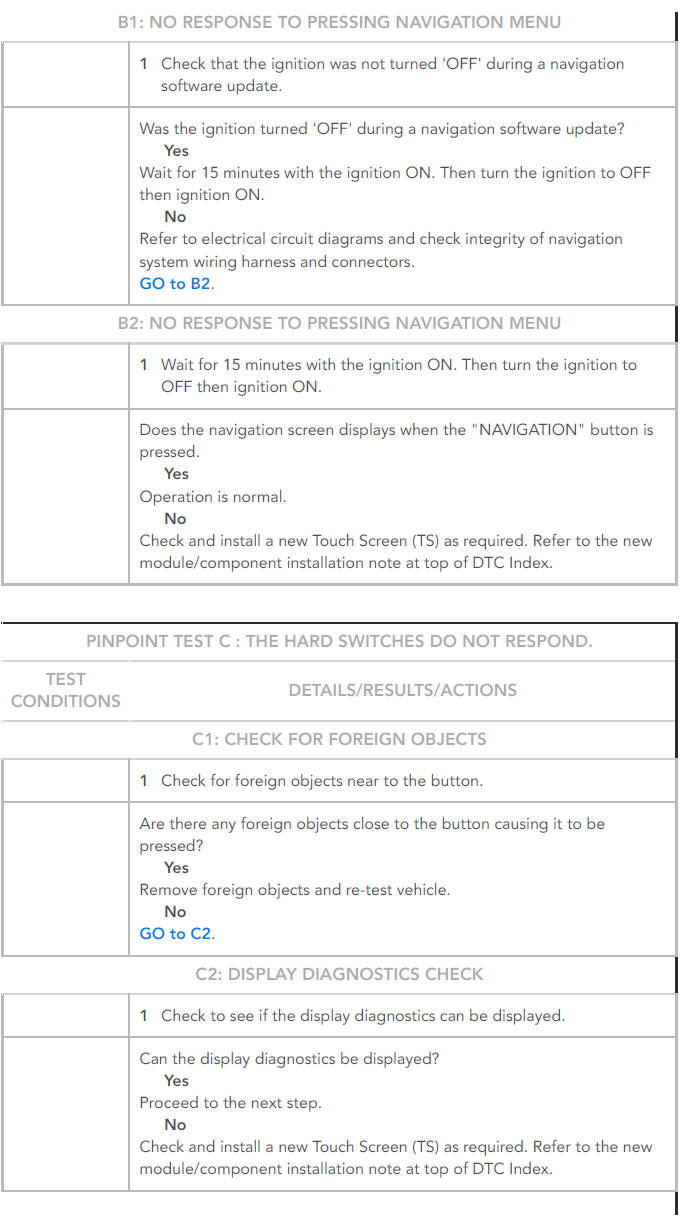
SYMPTOM:
The navigation screen does not display, even when the "NAVIGATION" button is pressed (screen does not change)
POSSIBLE CAUSE:
- Electrical harness open/short circuit, disconnected
- Component failure
ACTION:
- GO to Pinpoint Test B.
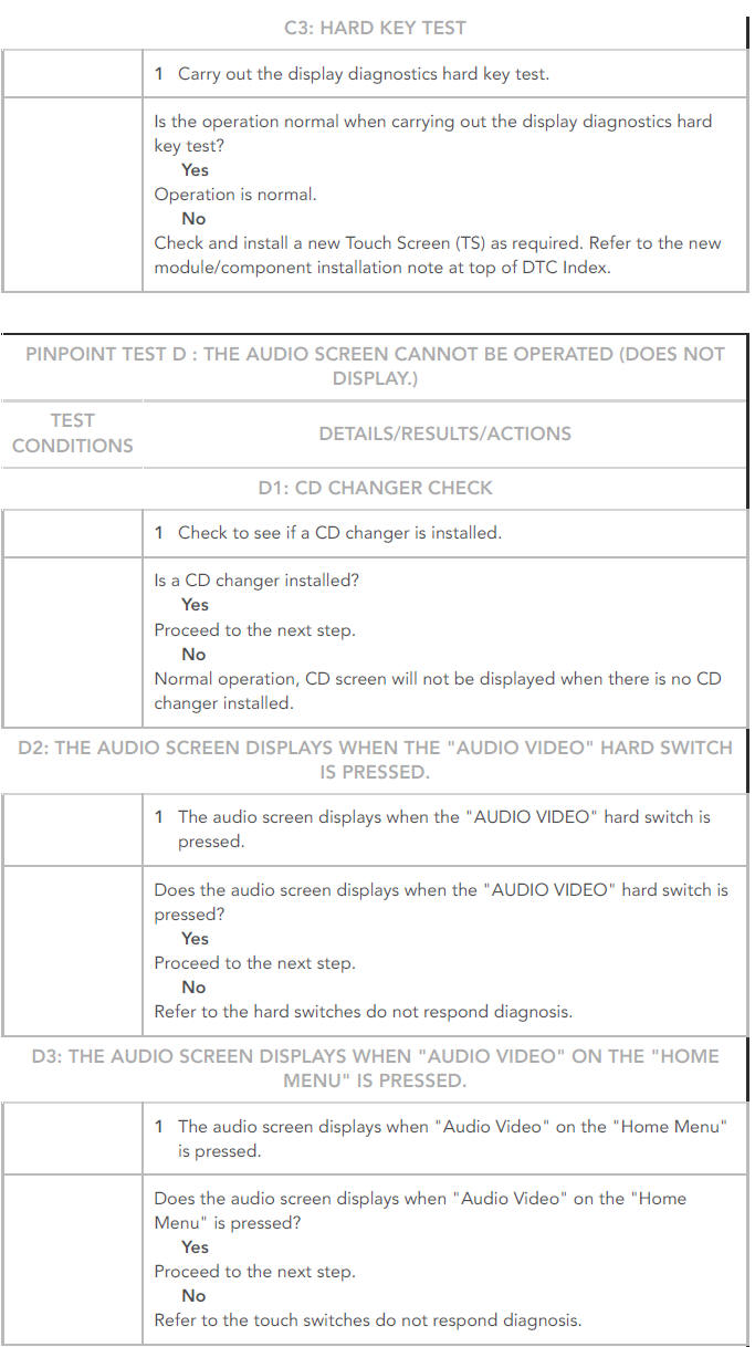
SYMPTOM:
The hard switches do not respond
POSSIBLE CAUSE:
- Component failure
- Switch failure
ACTION:
- GO to Pinpoint Test C.
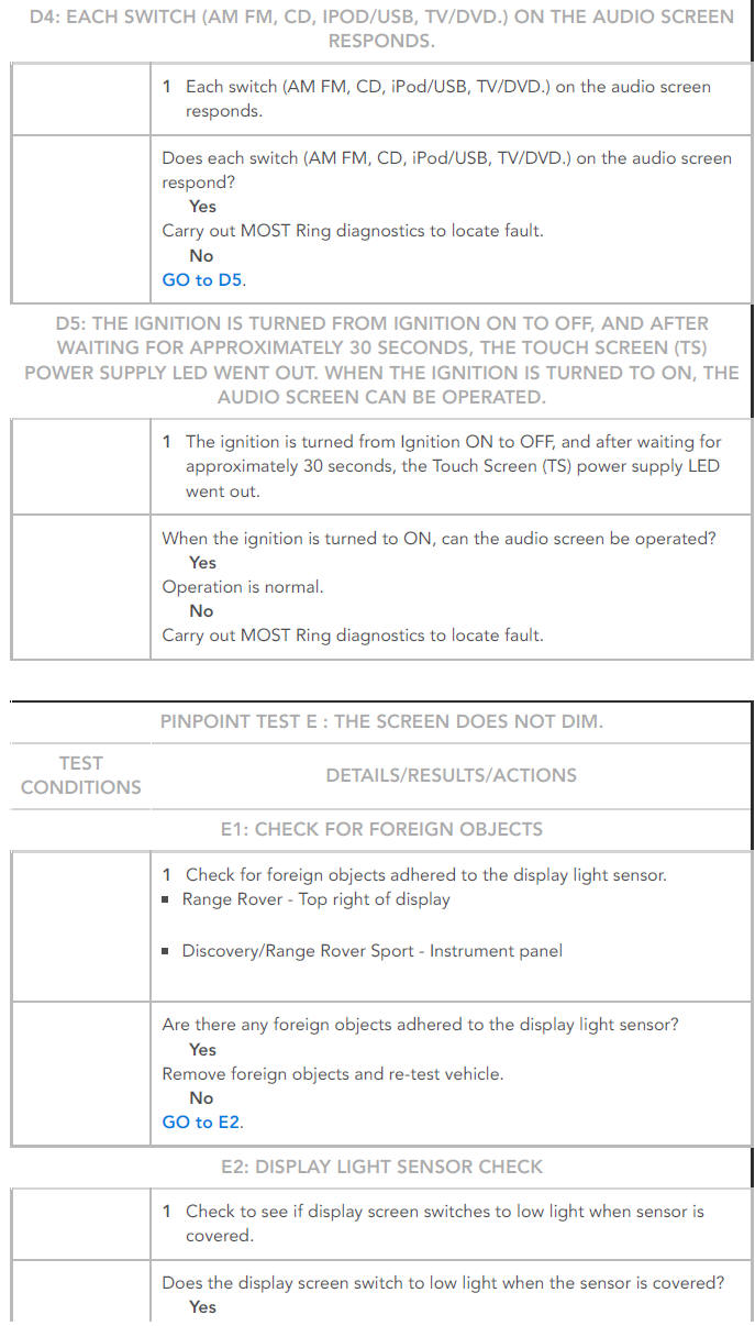
SYMPTOM:
The audio screen cannot be operated (does not display)
POSSIBLE CAUSE:
- Media Oriented System Transport (MOST) system
- Electrical harness open/short circuit, disconnected
ACTION:
- GO to Pinpoint Test D.
SYMPTOM:
The screen does not dim
POSSIBLE CAUSE:
- Electrical harness open/short circuit, disconnected
- Component failure
ACTION:
- GO to Pinpoint Test E.
SYMPTOM:
Noise on the screen, screen colour is abnormal
POSSIBLE CAUSE:
- Electrical harness open/short circuit, disconnected
- Component failure
ACTION:
- GO to Pinpoint Test F.
SYMPTOM:
The touch switches do not respond
POSSIBLE CAUSE:
- Electrical harness open/short circuit, disconnected
- Component failure
ACTION:
- GO to Pinpoint Test G.
SYMPTOM:
There is considerable deviation between the displayed vehicle position and the actual position
POSSIBLE CAUSE:
- Electrical harness open/short circuit, disconnected
- Component failure
ACTION:
- GO to Pinpoint Test H.
SYMPTOM:
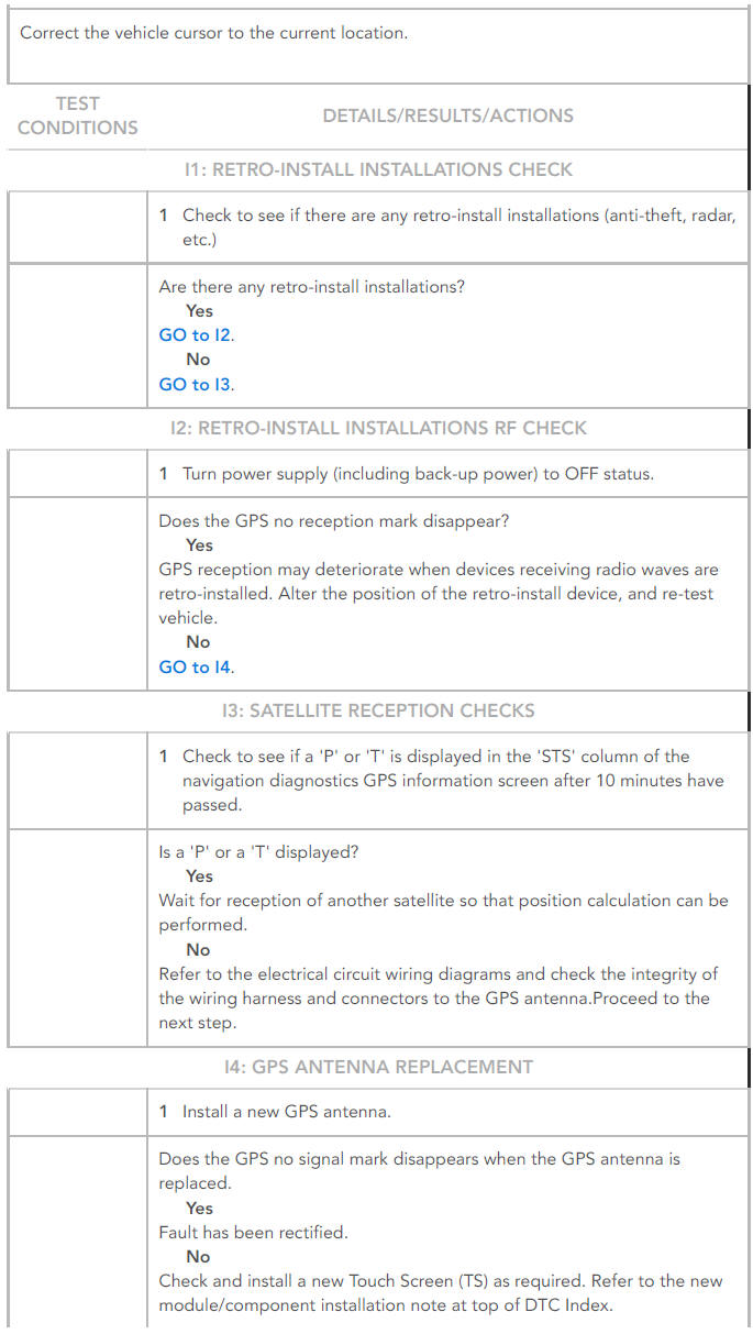
The GPS no reception mark does not disappear
POSSIBLE CAUSE:
- Electrical harness open/short circuit, disconnected
- Component failure
- No reception from satellite
ACTION:
- GO to Pinpoint Test I.
SYMPTOM:
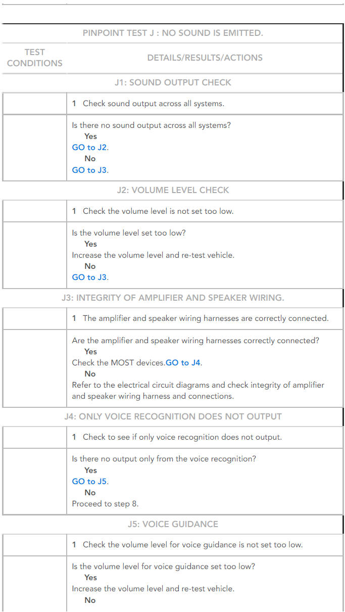
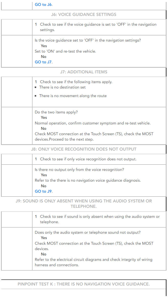
No sound is emitted
POSSIBLE CAUSE:
- Electrical harness open/short circuit, disconnected
- Component failure
- Incorrect system settings
ACTION:
- GO to Pinpoint Test J.
SYMPTOM:
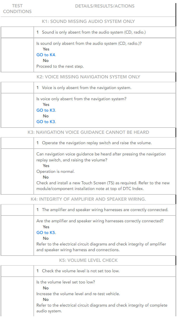
There is no navigation voice guidance
POSSIBLE CAUSE:
- Volume level set too low
- The amplifier and speakers are incorrectly connected
ACTION:
- GO to Pinpoint Test K.
SYMPTOM:
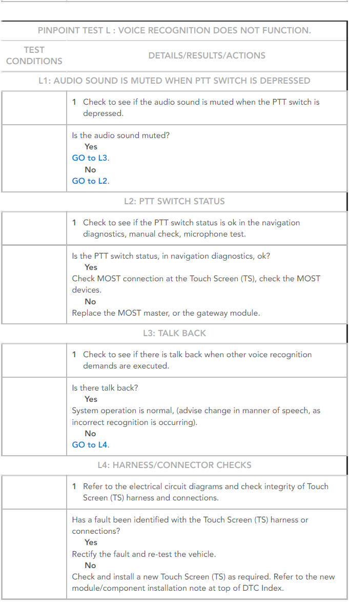
Voice recognition does not function
POSSIBLE CAUSE:
- Electrical harness open/short circuit, disconnected
- Component failure
ACTION:
- GO to Pinpoint Test L.
SYMPTOM:
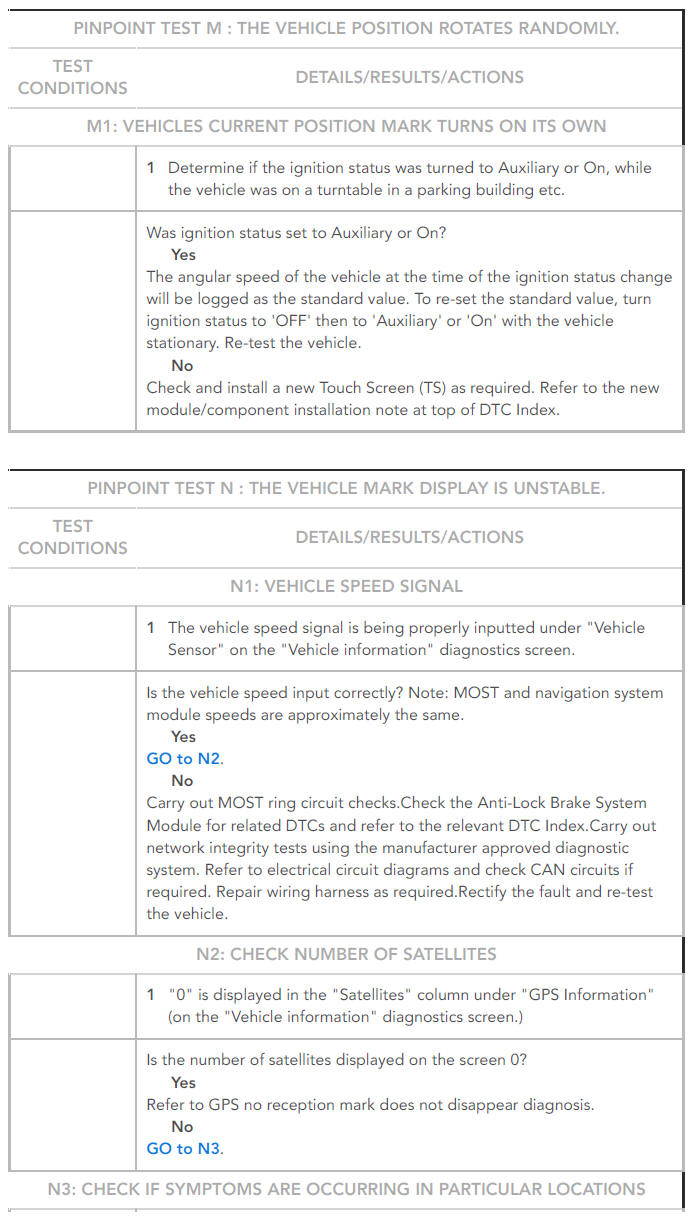
The vehicle position rotates randomly
POSSIBLE CAUSE:
- Electrical harness open/short circuit, disconnected
- Component failure
- Vehicle on a turntable in a parking building
ACTION:
- GO to Pinpoint Test M.
SYMPTOM:
The vehicle mark display is unstable
POSSIBLE CAUSE:
- Electrical harness open/short circuit, disconnected
- Component failure
- No reception from satellite
ACTION:
- GO to Pinpoint Test N.
SYMPTOM:
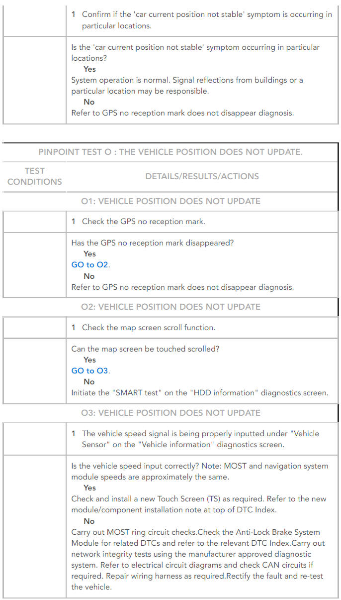
The vehicle position does not update
POSSIBLE CAUSE:
- HDD contaminated/damaged
- Electrical harness open/short circuit, disconnected
- Component failure
ACTION:
- GO to Pinpoint Test O.
SYMPTOM:
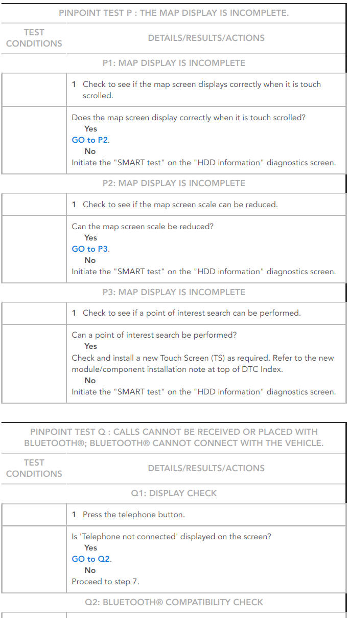
Calls cannot be received or placed with Bluetooth; Bluetooth cannot connect with the vehicle
POSSIBLE CAUSE:
- Incompatible
- Bluetooth telephone
- Incorrect initial connection settings
- Electrical harness open/short circuit, disconnected
- Component failure
ACTION:
- GO to Pinpoint Test Q.
SYMPTOM:
The map cannot be updated
POSSIBLE CAUSE:
- Refer to the "Navigation Update Tool" operation manual
ACTION:
- Refer to the "Navigation Update Tool" operation manual
SYMPTOM:
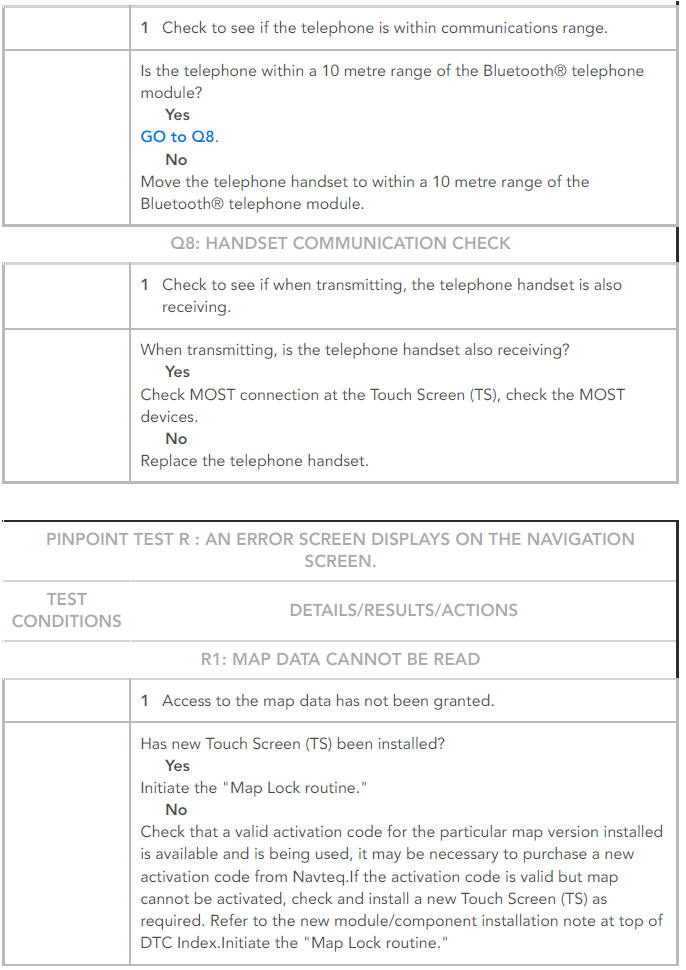
An error screen displays on the navigation screen
POSSIBLE CAUSE:
- Access to the map data has not been granted
ACTION:
- GO to Pinpoint Test R.
SYMPTOM:
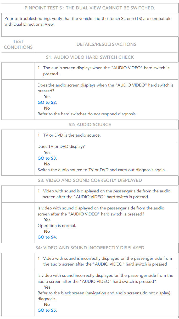
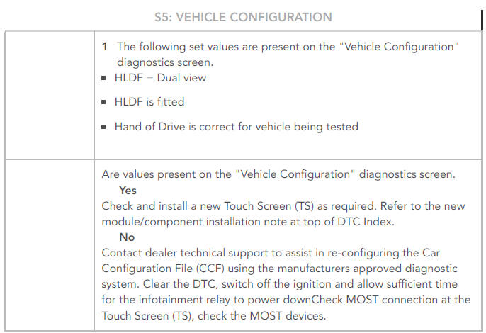
The dual view cannot be switched
POSSIBLE CAUSE:
- Incorrect car configuration data received
- Media Oriented System Transport (MOST) system
- Component failure
ACTION:
- Pinpoint Test S.
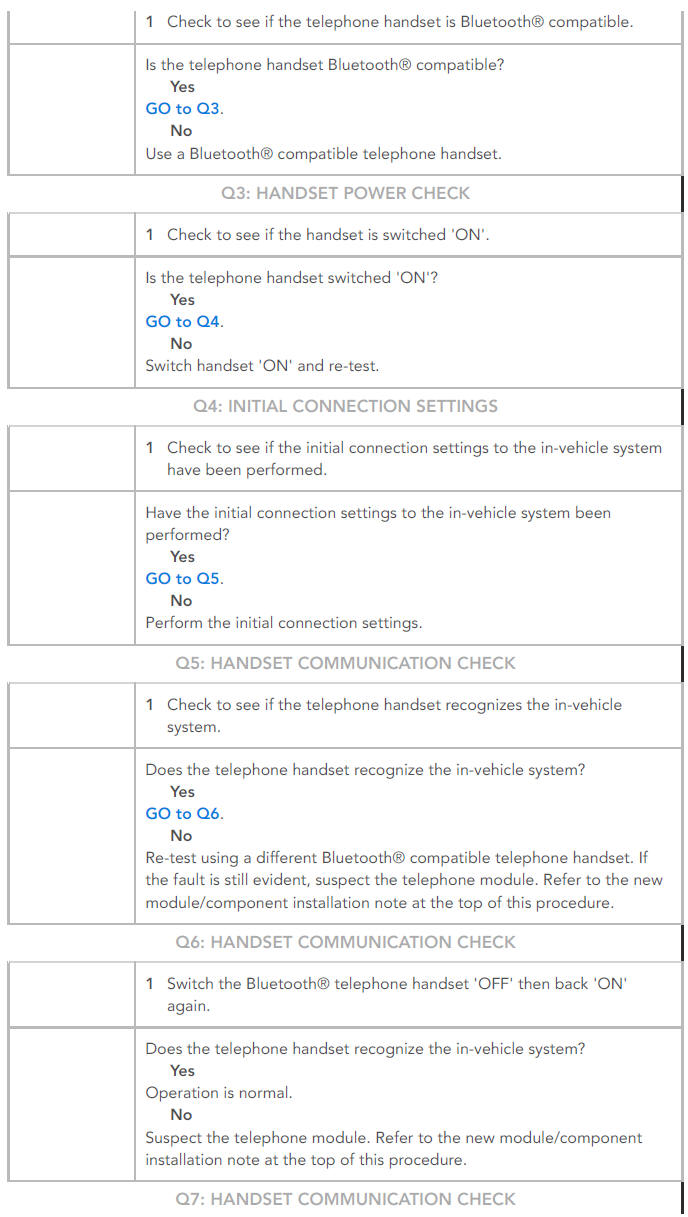
PINPOINT TESTS
NOTES:
- If the control module or a component is suspect and the vehicle remains under manufacturer warranty, refer to the Warranty Policy and Procedures manual (section B1.2), or determine if any prior approval Program is in operation, prior to the installation of a new module/component.
- The built in diagnostics are accessed as follows:
- 1.With the vehicle at rest, place the ignition switch "ON", or start the engine.
- 2. Press and hold the Touch Screen (TS) in the centre at the top of the screen for approximately 5 seconds and then press and hold the Touch Screen (TS) at the top left corner of the screen for approximately 5 seconds.
- 3. A 'Diag PIN Entry' box will appear' Type in the access code 753.
- 4.Once this code has been accepted the Diagnostic Menu screen will be displayed.
.jpg)
.jpg)
.jpg)
NOTE:
When re-confirming the symptoms after inspecting the wiring harness/connector, turn the ignition status to OFF, wait for the Audio power button LED on the display to turn OFF, then turn the ignition status to ON and run the diagnosis again from the beginning.
NOTE:
15 minutes are required for the program to update. If the ignition is accidentally turned OFF, turn the ignition ON again, and wait for 15 minutes.
.jpg)
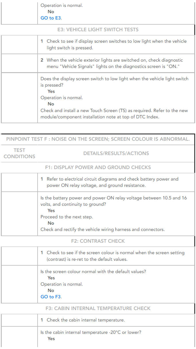
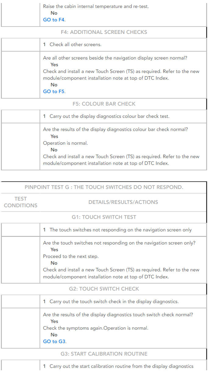

NOTE:
Refer to diagnostic menu "Vehicle Sensor" - Distance Calibration, this value should be approximately 200mm, a large deviation from this value indicates a speed signal fault or incorrect wheel size.
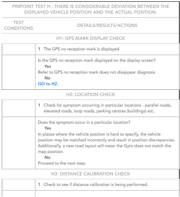
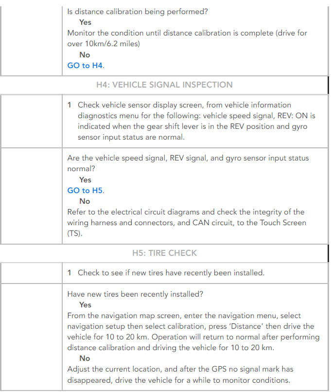
NOTES:
- Move the vehicle to an open area, radio waves from satellites may not be received inside buildings.
- Correct the vehicle cursor to the current location.

NOTE:
Prior to troubleshooting, verify that the vehicle and the Touch Screen (TS) are compatible with Dual Directional View.
DTC INDEX
For a complete list of all Diagnostic Trouble Codes (DTCs) that could be logged on this vehicle, please refer to Section 100-00.
REFER to: Diagnostic Trouble Code Index - DTC: Integrated Audio Module (IAM) (100-00 General Information, Description and Operation).

