Land Rover Discovery: Cylinder Block Components
.jpg)
- M6 bolt (13 off), M10 bolt (1 off)
- Engine front cover
- Cylinder block
- Lower timing chain cover
- M8 screw (16 off)
- M10 bolt (8 off)
- Dual mass flywheel (manual transmission) or drive plate (Automatic Transmission)
- Right dynamic balancer
- Left dynamic balancer
- Thrust washer (2 off)
- Upper main bearing (5 off)
- Crankshaft pulley / mass damper
- M10 bolt (4 off)
- Crankshaft
- Lower main bearing (5 off)
- Main bearing cap (5 off)
- M12 bolts (10 off) Main bearing caps
- Windage tray
- M6 screw (12 off)
- M8 screw (16 off)
- Oil pan
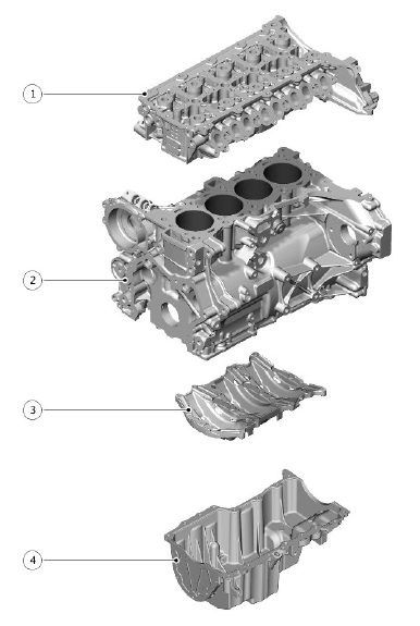
MAJOR STRUCTURAL COMPONENTS

- Cylinder head
- Cylinder block
- Windage tray
- Oil pan
CYLINDER BLOCK

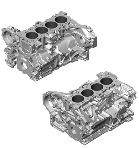
The deep skirt cast aluminum cylinder block is an in-line configuration. Thin wall, interference fit cast iron liners provide optimum weight, cylinder bore roundness and robustness. The low volume coolant jacket gives good warmup times. The cylinder block is a cross flow design with the coolant inlet to the cylinder head on the exhaust side and the coolant outlet from the cylinder head on the air inlet side.
Oil from the cylinder head drains back to the oil pan through open apertures; one located at the front of the cylinder block and one at the rear of the cylinder block between the timing chain and the lower timing chain cover.
A cast aluminum alloy, structural windage tray is bolted to the bottom of the cylinder block to further improve the cylinder block stiffness, minimize Noise, Vibration and Harshness (NVH) and help reduce oil foaming.
Various machining ports in the cylinder block are sealed with cup plugs and threaded plugs. Removal of these is not necessary for service procedures.
In cold climate markets a block heater is fitted to the cylinder block. The heater is screwed into a threaded bore on the cylinder block, which is normally sealed with a threaded plug.
CYLINDER NUMBERING
.gif)
The cylinders are numbered as shown, with cylinder 1 at the front of the engine

