Land Rover Discovery: Component location - Incontrol touch/ Incontrol plus
Land Rover Discovery (2009–2016) Service Manual / Electrical / Information and Entertainment System / Audio System / Component location - Incontrol touch/ Incontrol plus
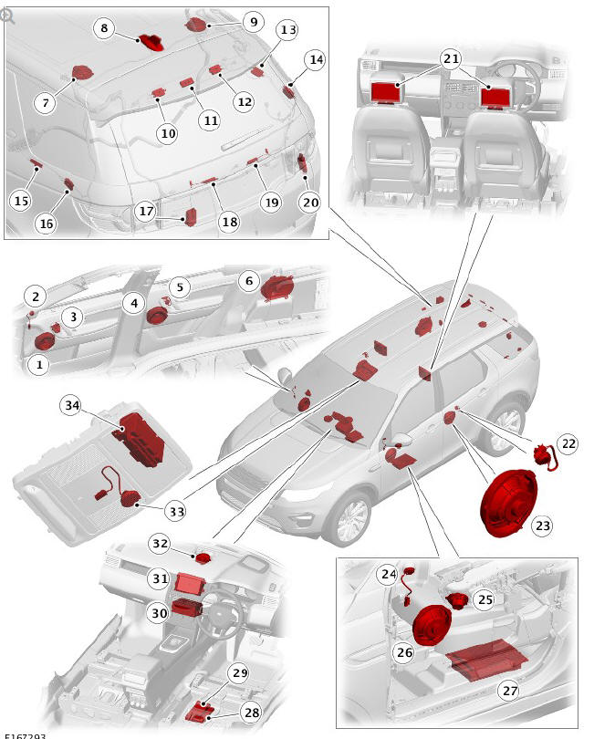
COMPONENT LOCATION - INCONTROL TOUCH - 6 SPEAKER AUDIO SYSTEM
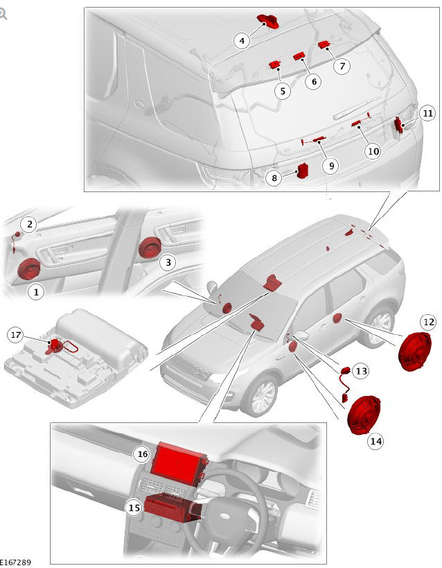
- Front right bass speaker
- Front right tweeter speaker
- Rear right bass speaker
- Roof pod
- Antenna amplifier FM/DAB-III
- Radio Frequency (RF) filter - High Mounted Stop Lamp (HMSL)
- Antenna amplifier AM/FM
- RF Filter - rear wiper motor relay
- RF Filter - Heated Rear Window positive (+)
- RF Filter - Heated Rear Window negative (-)
- Global Positioning System (GPS) signal splitter
- Rear left bass speaker
- Front left tweeter speaker
- Front left bass speaker
- Audio Head Unit (AHU)
- Touch Screen (TS)
- Microphone
COMPONENT LOCATION - INCONTROL TOUCH - 10 SPEAKER AUDIO SYSTEM
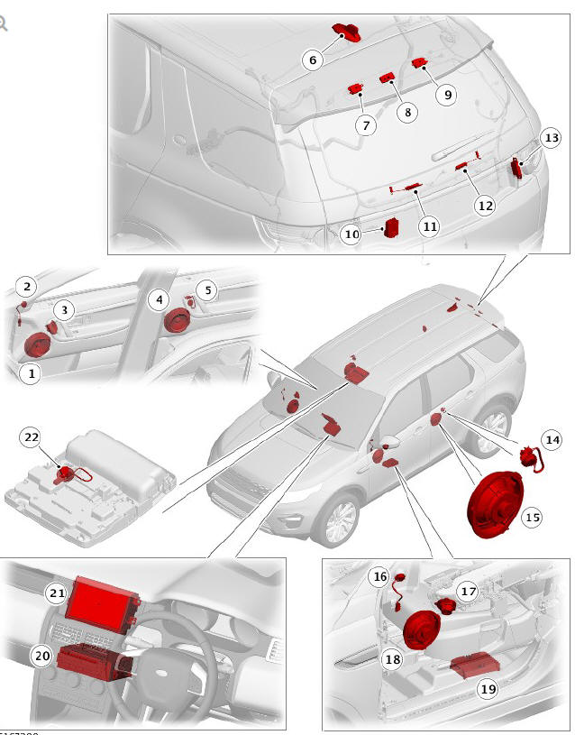
- Front right bass speaker
- Front right tweeter speaker
- Front right mid-range speaker
- Rear right bass speaker
- Rear right tweeter speaker
- Roof pod
- Antenna amplifier FM/Traffic Message Channel (TMC)/DAB-III
- Radio Frequency (RF) filter - High Mounted Stop Lamp (HMSL)
- Antenna amplifier AM/FM
- RF filter - rear wiper motor relay
- RF Filter - Heated Rear Window positive (+)
- RF Filter - Heated Rear Window negative (-)
- Global Positioning System (GPS) signal splitter
- Rear left tweeter speaker
- Rear left bass speaker
- Front left tweeter speaker
- Front left mid-range speaker
- Front left bass speaker
- Audio Amplifier Module (AAM)
- Audio Head Unit (AHU)
- Touch Screen (TS)
- Microphone
COMPONENT LOCATION - INCONTROL TOUCH - 11 SPEAKER AUDIO SYSTEM
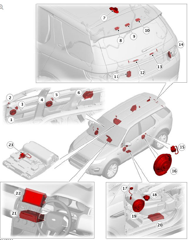
- Front right bass speaker
- Front right tweeter speaker
- Front right mid-range speaker
- Rear right bass speaker
- Rear right tweeter speaker
- Sub-woofer speaker
- Roof pod
- Antenna amplifier FM/TMC/DAB-III
- Radio Frequency (RF) filter - High Mounted Stop Lamp (HMSL)
- Antenna amplifier AM/FM
- RF filter - rear wiper motor relay
- RF Filter - Heated Rear Window positive (+)
- RF Filter - Heated Rear Window negative (-)
- Global Positioning System (GPS) signal splitter
- Rear left tweeter speaker
- Rear left bass speaker
- Front left tweeter speaker
- Front left mid-range speaker
- Front left bass speaker
- Audio Amplifier Module (AAM)
- Audio Head Unit (AHU)
- Touch Screen (TS)
- Microphone
COMPONENT LOCATION - INCONTROL PLUS - 11 SPEAKER AUDIO SYSTEM
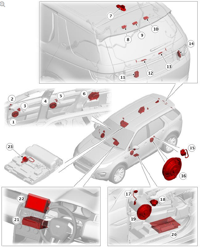
- Front right bass speaker
- Front right tweeter speaker
- Front right mid-range speaker
- Rear right bass speaker
- Rear right tweeter speaker
- Sub-woofer speaker
- Roof pod
- Antenna amplifier FM/TMC/DAB-III
- Radio Frequency (RF) filter - High Mounted Stop Lamp (HMSL)
- Antenna amplifier AM/FM
- RF filter - rear wiper motor relay
- RF Filter - Heated Rear Window positive (+)
- RF Filter - Heated Rear Window negative (-)
- Global Positioning System (GPS) signal splitter
- Rear left tweeter speaker
- Rear left bass speaker
- Front left tweeter speaker
- Front left mid-range speaker
- Front left bass speaker
- Audio Amplifier Module (AAM)
- Integrated Audio Module (IAM)
- Touch Screen (TS)
- Microphone
COMPON ENT LOCATION - INCONTROL PLUS - 17 SPEAKER AUDIO SYSTEM
- Front right bass speaker
- Front right tweeter speaker
- Front right mid-range speaker
- Rear right bass speaker
- Rear right tweeter speaker
- Sub-woofer speaker
- Left headliner co-axial speaker
- Roof pod
- Right headliner co-axial speaker
- Antenna amplifier FM/TMC/DAB-III
- Radio Frequency (RF) filter - High Mounted Stop Lamp (HMSL)
- Antenna amplifier AM/FM
- Television (TV) antenna amplifier
- TV antenna amplifier
- TV antenna amplifier
- TV antenna amplifier
- RF filter - rear wiper motor relay
- RF Filter - Heated Rear Window positive (+)
- RF Filter - Heated Rear Window negative (-)
- Global Positioning System (GPS) signal splitter
- Rear Seat Entertainment (RSE) screen - left/right
- Rear left tweeter speaker
- Rear left bass speaker
- Front left tweeter speaker
- Front left mid-range speaker
- Front left bass speaker
- Audio Amplifier Module (AAM)
- Rear Seat Entertainment (RSE) control module (Ref only)
- Satellite Radio Control Module (SRCM) (SDARS NAS only)
- Integrated Audio Module (IAM)
- Touch Screen (TS)
- Instrument panel co-axial speaker
- Microphone
- Headphone transmitter
READ NEXT:
 Audio System - Overview
The audio system is available in five versions. Three of the systems use an
Audio Head Unit (AHU) and two use an Integrated Audio Module (IAM).
All systems are controlled using an 8" Touch Screen (TS
Audio System / Description
TOUCH SCREEN (TS)
Touch Screen - Audio Head Unit - InControl Touch Audio Systems
Infotainment system On/Off switch
'Camera' switch
'Parking Aid' On/Off switch (if fitted)
'General Settings'
'P
Portable Audio Interface Panel
For InControl Touch systems with Navigation, voice control or telephone
For InControl Touch Plus audio system and InControl Touch Plus with
Meridian
surround system
For InControl Touch audio
SEE MORE:
All Wheel Drive Control Module (AWDCM)
The AWDCM is located at the front right side of the RDU, adjacent to the
drive flange. The AWDCM is attached to the RDU casing and secured with
screws.
Two electrical connectors provide the interface between the AWD valve
block and the vehicle systems. The upper connector provides the
connections
Proximity Cameras
Proximity Camera Coverage Zones
Front Proximity Camera
Right Proximity Camera
Rear Proximity Camera
Left Proximity Camera
The proximity camera system has four cameras that are located in the
following:
One camera located in the front bumper.
One camera in each of the door mirror assembl
© 2019-2025 Copyright www.lrdisc.com
