Land Rover Discovery: Audio Unit (G1785533) / Removal and Installation
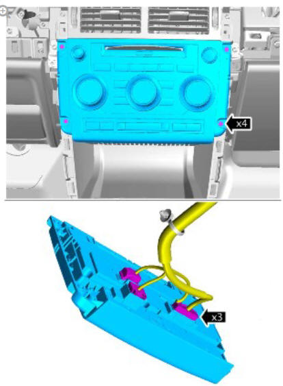
REMOVAL
CAUTION:
Use a suitable trim tool.
NOTE:
Removal steps in this procedure may contain installation details.
Disconnect the battery ground cable.
Refer to: Specifications (414-01 Battery, Mounting and Cables, Specifications).
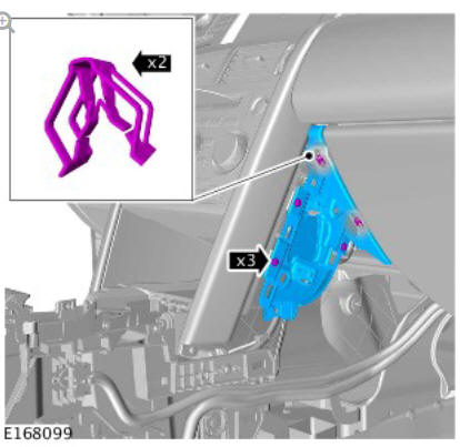
Refer to: Floor Console Upper Section (501-12 Instrument Panel and Console, Removal and Installation).
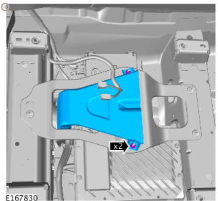
NOTE:
Repeat the step for the other side.
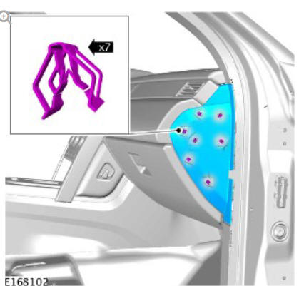
NOTE:
Repeat the step for the other side.
Torque: 1.5 Nm
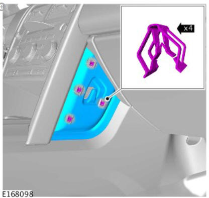
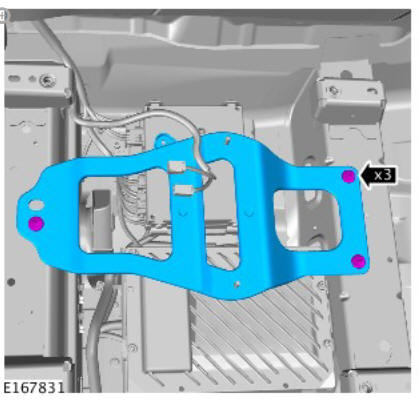
NOTE:
Repeat the step for the other side.
Torque: 1.5 Nm
Torque: 6 Nm
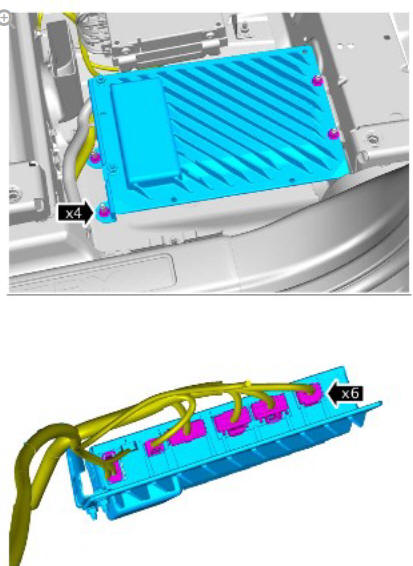
Torque: 1.5 Nm
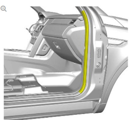
CAUTION:
Extreme care must be taken when removing and installing the trim. Excessive force may result in damage to the component.
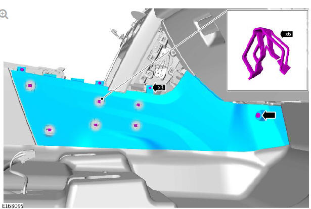
NOTE:
Repeat the step for the other side.
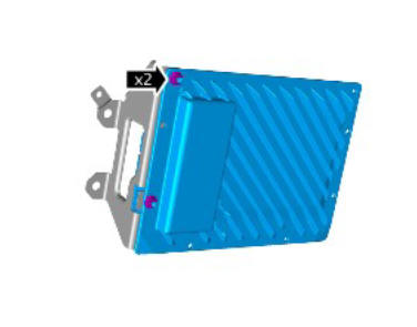
Torque: 1.5 Nm
Torque: 1.5 Nm
Torque: 6 Nm
INSTALLATION
NOTE:
If a new component has been installed, configure using Land Rover approved diagnostic equipment.
To install, reverse the removal procedure.
If a new unit is fitted the navigation system will require setting up with the country and region, follow the on screen instructions within the set up menu.
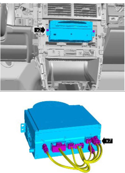
Audio Unit Amplifier (G1785142) / Removal and Installation
REMOVAL
NOTE:
Removal steps in this procedure may contain installation details.
Disconnect the battery ground cable.
Refer to: Specifications (414-01 Battery, Mounting and Cables, Specifications).
Remove the left front seat.
Refer to: Front Row Seat - Vehicles With: Power Seats (501-10 Seating, Removal and Installation).
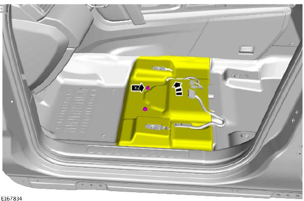
Torque: 9 Nm
Torque: 9 Nm
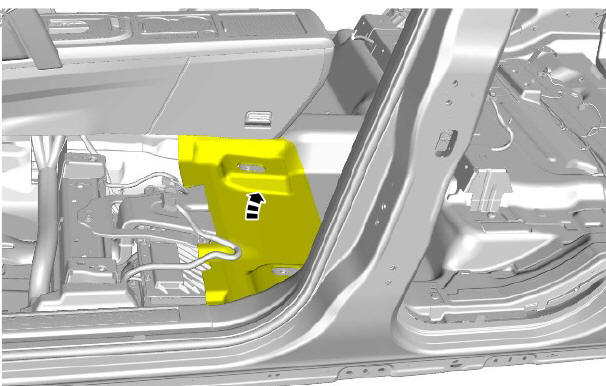
NOTE:
Do not disassemble further if the component is removed for access only.
Torque: 9 Nm
INSTALLATION
- To install, reverse the removal procedure.
READ NEXT:
 Cellular Phone
COMPONENT LOCATION - INCONTROL TOUCH AUDIO SYSTEMS
Microphone
Audio Amplifier Module (AAM)
Audio Head Unit (AHU)
Touch Screen (TS)
COMPONENT LOCATION - INCONTROL TOUCH PLUS AND INCONTROL TOUCH
Diagnosis and Testing Cellular Phone
PRINCIPLE OF OPERATION
For a detailed description of the Mobile phone system and operation, refer
to the relevant Diagnosis and Testing section of the workshop manual.
REFER to: (415-01 Information a
Diagnosis and Testing Information and Entertainment System
PRINCIPLE OF OPERATION
For a detailed description of the information and entertainment system,
refer to the relevant description and operation sections in the workshop
manual.
INSPECTION AND VERIFICAT
SEE MORE:
Starting System - Ingenium
i4 2.0l Diesel / Diagnosis and Testing
PRINCIPLES OF OPERATION
For a detailed description of the Starting System, refer to the relevant
Description and Operation section in the workshop manual. REFER to:
Starting System (303-06C Starting System - GTDi 2.0L Petrol/GTDi 2.0L
Petrol - SULEV, Description and Operation).
INSPECTION AND VERIFI
Seats - Vehicles With- Climate Controlled Seats - Pinpoint
Tests
WARNING:
Before work is carried out, make the air bag supplemental restraint
system safe. For additional information, refer to Standard Workshop
Practices section of workshop manual
NOTES:
The climate controlled seat's (heat and cool) functions will only
operate when the vehicle's engine is runni
