Land Rover Discovery: Anti-lock Control Front Wheel Speed Sensor (G1807250) / Removal and Installation
REMOVAL
NOTE:
Removal steps in this procedure may contain installation details.
WARNING:
Make sure to support the vehicle with axle stands.
Raise and support the vehicle.
Refer to: Fender Splash Shield (501-02 Front End Body Panels,
Removal and Installation).
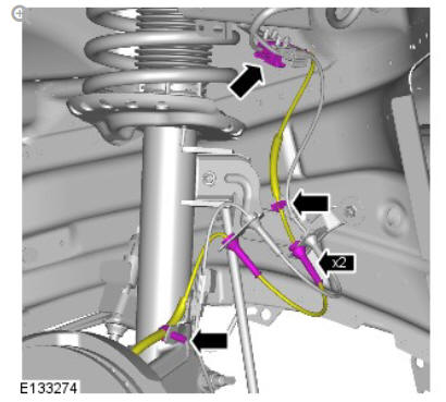
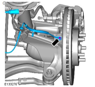
Torque: 5 Nm
INSTALLATION
CAUTION:
Make sure that the mating faces are clean and free of foreign material.
To install, reverse the removal procedure.
Anti-lock control rear wheel speed sensor (G1781461) removal and installation
REMOVAL
NOTES:
- Removal steps in this procedure may contain installation details.
- Left shown, right is similar.
WARNING:
Make sure to support the vehicle with axle stands.
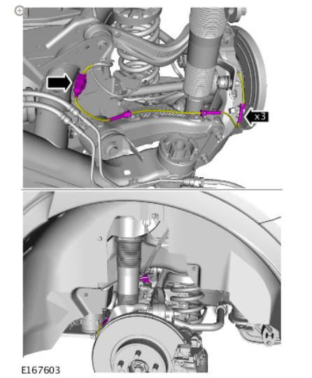
Raise and support the vehicle.
Refer to: Wheel and Tire (204-04, Removal and Installation).
CAUTION:
Before disconnecting or removing the components, make sure the area around the joint faces and connections are clean.
CAUTIONS:
- Make sure that the component is clean, free of foreign material and lubricant.
- Make sure that the sensor tip is clean and free of foreign material.
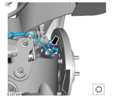
Torque: 9 Nm
INSTALLATION
To install reverse the removal procedure.
Anti-lock control - stability assist accelerometer (G1791760) removal and installation
REMOVAL
Refer to: Restraints Control Module (501-20B Supplemental Restraint System, Removal and Installation).
INSTALLATION
To install, reverse the removal procedure.
If a new component has been installed, configure using Land Rover approved diagnostic equipment.
READ NEXT:
 Anti-lock Control - Traction Control / Description and Operation
COMPONENT LOCATION - SHEET1 OF 2
NOTE:
Right Hand Drive (RHD) illustration shown, Left Hand Drive (LHD)
illustration similar
Rear right wheel speed sensor
Rear left wheel speed sensor
Front righ
Dynamic Stability Control (DSC) Switch
DESCRIPTION
The Dynamic Stability Control (DSC) switch is a non-latching switch installed
in the floor console, forward of the selector lever (for manual transmission
vehicles) or Transmission Contr
Wheel Speed Sensors
Retaining screw
Wheel speed sensor
Bearing seal and magnetic encoder ring
Wheel bearing
Wheel hub
An active wheel speed sensor is installed in each wheel knuckle, and
provides the Anti-lock B
SEE MORE:
Using the seat belts
Putting on a seat belt: Draw the belt
out smoothly, making sure that the
seat position and your position on the
seat are correct.
When correctly positioned, the seat
belt should cross the collar bone at the
mid-point between the neck and the
end of your shoulder.
Where possible, rear se
Pairing and connecting a bluetooth phone or device
A paired phone or device can be
connected for different uses; phone or
music. Pairing is normally required only
once.
When the ignition is switched on, the
vehicle automatically tries to re-connect
to a previously paired Bluetooth phone
or device, if it is within range of the
vehicle.
If automatic
