Land Rover Discovery: Anti-lock Control Anti-lock Brake System Module (G1807249) / Removal and Installation
Land Rover Discovery (2009–2016) Service Manual / Chassis / Chassis-Brake-System / Anti-lock Control Anti-lock Brake System Module (G1807249) / Removal and
Installation
REMOVAL
CAUTIONS:
- If brake fluid is spilt on the paintwork, the affected area must be immediately washed down with cold water.
- Make sure that all openings are sealed. Use new blanking caps.
NOTES:
- Removal steps in this procedure may contain installation details.
- LHD illustration shown, RHD is similar.
All vehicles
WARNING:
Make sure to support the vehicle with axle stands.
Raise and support the vehicle.
Refer to: Plenum Chamber (412-01 Climate Control, Removal and Installation).
Refer to: Battery Tray (414-01 Battery, Mounting and Cables, Removal and Installation).
Vehicles with petrol engine
Vehicles with diesel engine
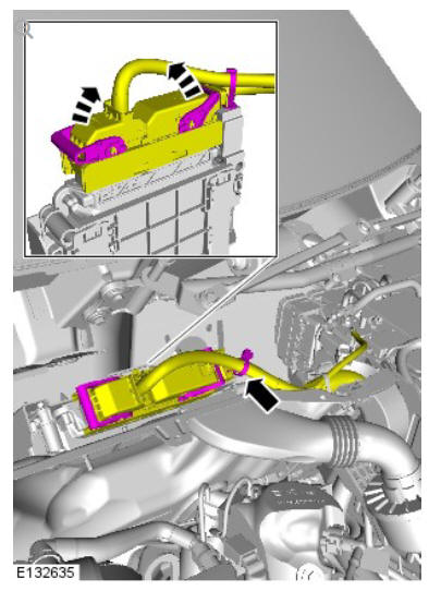
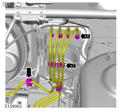
All vehicles
NOTE:
Component shown removed for clarity.
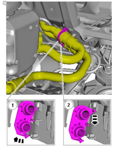
Torque: 17 Nm
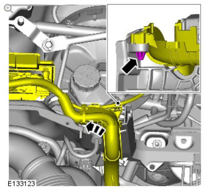
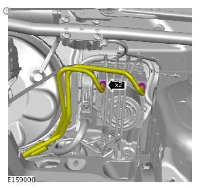
WARNING:
Fluid loss is unavoidable, use absorbent cloth or a container to collect the fluid.
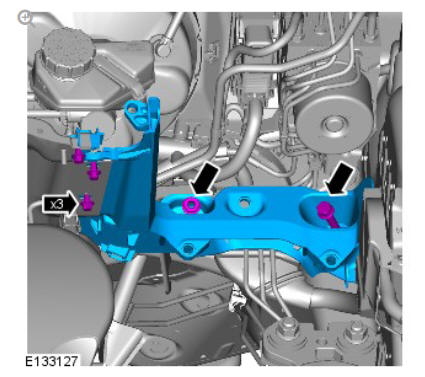
Torque: 17 Nm
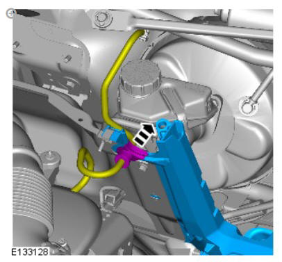
Torque: 14 Nm
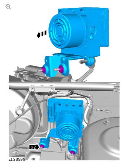
Torque: 9 Nm
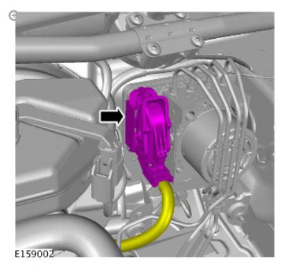
NOTE:
Do not disassemble further if the component is removed for access only.
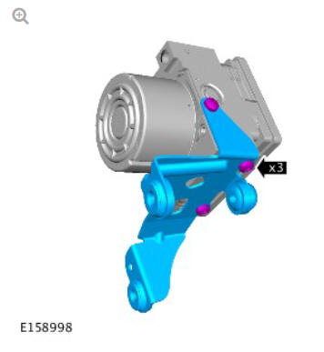
Torque: 9 Nm
INSTALLATION
NOTE:
Remove and discard all blanking caps.
- To install, reverse the removal procedure.
- Refer to: Brake System Pressure Bleeding (206-00 Brake System - General Information, General Procedures).
- If a new component has been installed, configure using Land Rover approved diagnostic equipment.
READ NEXT:
 Anti-lock Control Front Wheel Speed Sensor (G1807250) / Removal and
Installation
Anti-lock Control Front Wheel Speed Sensor (G1807250) / Removal and
Installation
REMOVAL
NOTE:
Removal steps in this procedure may contain installation details.
WARNING:
Make sure to support the vehicle with axle stands.
Raise and support the vehicle.
Refer to: Fender Splash Shiel
Anti-lock Control - Traction Control / Description and Operation
COMPONENT LOCATION - SHEET1 OF 2
NOTE:
Right Hand Drive (RHD) illustration shown, Left Hand Drive (LHD)
illustration similar
Rear right wheel speed sensor
Rear left wheel speed sensor
Front righ
Dynamic Stability Control (DSC) Switch
DESCRIPTION
The Dynamic Stability Control (DSC) switch is a non-latching switch installed
in the floor console, forward of the selector lever (for manual transmission
vehicles) or Transmission Contr
SEE MORE:
Side Panel Sheet
Metal Repairs 'B'
Pillar Outer
Panel (G1770904) - Removal
REMOVAL
NOTE:
In this procedure the B-pillar outer panel is installed in conjunction
with:
Front door
Rear door
Front seat
Rear seat cushion
Front safety belt retractor
Front scuff plate trim panel
Rear scuff plate trim panel
Headliner
Side air curtain module
The B-pillar outer panel
Blind spot monitoring
BLIND SPOT MONITOR (BSM)
The Blind Spot Monitor (BSM)
system is a supplement to, not a
replacement for, a safe driving
style and use of the exterior and
rear-view mirrors. The system may
not function under all speeds,
weather and road conditions.
The BSM may not be able to give
adequate warning of v
© 2019-2025 Copyright www.lrdisc.com
