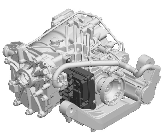
Land Rover Discovery: All Wheel Drive Control Module (AWDCM) / Description

The AWDCM is located at the front right side of the RDU, adjacent to the drive flange. The AWDCM is attached to the RDU casing and secured with screws.
Two electrical connectors provide the interface between the AWD valve block and the vehicle systems. The upper connector provides the connections to the RDU pump actuator and the control solenoids. The lower connector provides the interface with the other vehicle system modules.
The AWDCM receives high speed MultiCAN (controller area network) bus signals from the chassis and powertrain systems buses.
The AWDCM monitors the electrical signals to the RDU pump actuator and the control solenoids. The AWDCM software can check for short and open circuits, monitor current consumption and can perform plausibility check for incorrect signals. It can also detect leaks, blockages and failures by monitoring hydraulic pressure against the expected system responses.
Hydraulic pressure is detected from RDU Pump actuator rotational speed, detected via feedback from the actuator Hall sensors, and current consumption. Low fluid pressure is detected if the motor spins faster than expected. High fluid pressure or blockage is detected of motor speed is low and current consumption is high.
Failures of the control solenoids are detected if the hydraulic system pressurises faster or slower than expected, which is detected from monitoring the fluid pressure.
The spool valves are also monitored. If a spool valve has failed to open, low fluid pressure will be detected by monitoring the RDU pump actuator.
Inputs from other vehicle systems are received via the high speed CAN signals from the chassis and powertrain systems buses. This information is used to determine connect and disconnect states and speed of connection.
This is to ensure that the correct state of connection occurs to provide maximum handling and dynamic improvements and optimum fuel economy.
Outputs from the AWDCM provide information for the driver on the system status. This is displayed in the Touch Screen (TS) or the Instrument cluster (IC). The IC provides warning messages and warning chimes. The TS provides system status displays showing PTU and RDU operation and FWD and AWD connection.
If a failure occurs, the system will only operate in FWD and a warning message will be displayed.
Fault codes are stored and can be retrieved using an approved Land Rover diagnostic system.
DRIVER INFORMATION
Information is available to driver for system status. The information is output from the AWDCM on the high speed CAN chassis systems bus to the Touch Screen (TS) and the Instrument Cluster (IC).
Operational information is available in the TS 4x4i display, and shows the current operating condition of the Active Driveline. The following image shows TS displays for FWD and AWD and the possible combinations for the RDU.
4x4i Display in Touch Screen
.jpg)
- Active Driveline Disconnect AWD - displayed when Active Driveline is in an AWD status for optimum traction and dynamic performance
- Active Driveline Disconnect FWD - displayed when Active Driveline is in FWD status for optimum fuel economy
- Active Driveline OFF - displayed when the engine is off, or when a fault condition prevents the Active Driveline status from being displayed
Warning information is displayed in the IC. Warning message '2 wheel drive only - traction reduced' will be displayed for overheat in the message center and accompanied by a warning chime. If a system fault occurs, the message ' 4 wheel drive fault - 2 wheel drive only' will be displayed, accompanied by a warning chime.

