Land Rover Discovery: Variable Сamshaft Еiming (VCT) - Exhaust Camshaft Only
.jpg)
- Exhaust VCT solenoid
- Exhaust VCT actuator
The timing of the exhaust camshaft can be adjusted independently by an oil pressure controlled torsional assist VCT system. The VCT solenoid which is controlled electrically determines the position of the VCT actuator which has a direct interface with the exhaust camshaft.
The VCT actuator is located on the exhaust camshaft at the rear of the engine and is secured with a center bolt. The center bolt contains an oil control valve. A slot in the VCT actuator locates over a timing pin on the exhaust camshaft and is used to maintain the timing of the VCT actuator relative to the exhaust camshaft lobe position.
.jpg)
- Solenoid coil
- Solenoid core
- VCT solenoid assembly
- Solenoid pintle pin
- Center bolt
- Pressurized engine oil
- Filter
- Rotor
- VCT actuator assembly
- Spool valve
The VCT actuator is operated by a VCT solenoid which is controlled by the Engine Control Module (ECM). The ECM can operate the VCT solenoid to move the pintle pin to a pre-determined position to control the flow of pressurized engine oil into the VCT actuator When advance or retard of the exhaust camshaft timing is required, the VCT solenoid operates, extending the pintle pin and moving the spool valve to direct pressurized engine oil into one side or the other of the central rotor chambers in the VCT actuator. The solenoid pintle moves towards the spool valve located in the center bolt and makes contact.
Further movement of the solenoid pintle pin will push the spool valve into a known (controlled) position and oil will pass through channels within the center bolt into the VCT actuator chambers. The pressurized engine oil rotates the internal rotor in the VCT actuator which is secured to the exhaust camshaft. This in turn changes the engine timing. The total available camshaft advance adjustment is 50º Crankshaft Angle towards advance.
The exhaust camshaft VCT actuator has three hydraulic chambers. Residual camshaft torque is used to ensure the VCT actuator is returned to the 'base' position as quickly as possible. The pressurized engine oil is supplied from the engine variable flow oil pump with integral vacuum pump and must be mapped to deliver a controlled oil pressure to the VCT actuator to ensure VCT performance and response times are maintained.
There is no VCT system on the intake camshaft.
LUBRICATION SYSTEM
.jpg)
- Oil filter and housing assembly
- Turbocharger oil feed pipe
- Turbocharger oil drain pipe
- Engine oil cooler
- Piston cooling oil jets solenoid
- Piston cooling oil jets
- Variable flow oil pump with integral vacuum pump
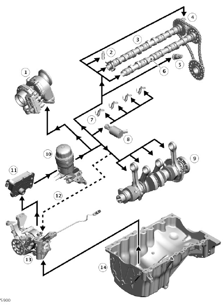
Lubrication System Flow Diagram

- Turbocharger
- Hydraulic lash adjusters
- Exhaust camshaft
- Variable camshaft timing (VCT) actuator
- Secondary chain tensioner
- Inlet camshaft
- Piston cooling oil jets
- Piston cooling oil jets solenoid
- Crankshaft
- Oil filter and housing assembly
- Engine oil cooler
- Oil gallery pressure feedback to variable flow oil pump with integral vacuum pump
- Variable flow oil pump with integral vacuum pump
- Oil pan
Oil is drawn from the oil pan and pressurized by the variable flow oil pump with integral vacuum pump. The output from the variable flow oil pump with integral vacuum pump is then filtered through the oil filter and housing assembly and distributed through internal oil passageways in the cylinder block and cylinder head.
The output from the oil filter is distributed through oil galleries in the cylinder heads and the cylinder block. All moving parts are lubricated by pressure or splash oil. Pressurized oil is also provided for the VCT system, the piston cooling jets, turbocharger, hydraulic lash adjusters and chain tensioner. The gallery pressure is fed back to the variable flow oil pump via a drilling in the cylinder block and the variable flow oil pump uses this pressure signal to regulate the oil flow and pressure. The Engine Control module (ECM) can control the variable flow oil pump electrically, requesting a pressure held in engine oil pressure map which is dependent on engine speed and load.
The oil returns to the oil pan under gravity. Large drain holes through the cylinder head and the cylinder block ensure the rapid return of the oil to the oil pan. System replenishment is through the oil filler cap on the camshaft cover. An oil drain plug is installed in the side of the oil pan.

