Land Rover Discovery: Glow Plug System - Ingenium i4 2.0l Diesel / Description and Operation
COMPONENT LOCATION
.jpg)
- Glow plug warning indicator
- Engine Control Module (ECM)
- Glow plug control module
- Glow Plugs (4 off)
OVERVIEW
A glow plug is installed in the inlet side of each cylinder to heat the combustion chambers before and during cranking. This helps cold starting and reduces emissions and engine noise when idling from a cold engine.
A glow plug control module powers each glow plug individually. The glow plug control module incorporates diagnostic functions for the individual glow plugs and reports the diagnostic status by means of an output signal to the Engine Control Module (ECM). An input signal from the ECM determines the power level applied to the glow plugs by the glow plug control module.
Each glow plug is grounded through its fixing in the cylinder head. The ECM controls the operation of the glow plug relay which is located in the glow plug control unit. The glow plug relay controls the illumination of the glow plug indicator in the Instrument Cluster (IC).
DESCRIPTION
GLOW PLUG

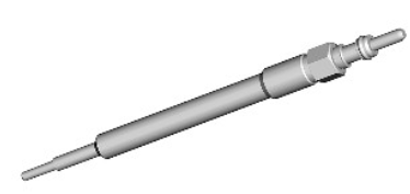
The glow plugs are a low voltage ceramic type, At the tip of the tubular heating element is the heater coil. Behind the heater coil, and connected in series, is a control coil. The control coil regulates the current to the heater coil to safeguard against overheating.
It is important that the correct torque setting is used when refitting a glow plug into the cylinder head.
GLOW PLUG CONTROL MODULE
.jpg)
The glow plug control module has a battery power supply from the Battery Junction Box (BJB) and an earth lead connection. The Engine Control Module (ECM) controls the operation of the glow plug relay which is located in the glow plug control module. The glow plug relay controls the illumination of the glow plug indicator in the Instrument Cluster (IC).
The system is a low-voltage glow system. At 7 volts, the nominal voltage of the sheathed-element glow plugs is significantly lower than the 12 volts of the main electrical circuit.
In there is a glow plug failure, the engine may be difficult to start and you may see excessive smoke emissions after starting.
OPERATION
There are three phases of glow plug heating:
- Pre-heating
- Crank heating
- Post-heating
The Engine Control Module (ECM) determines the heating times from the Engine Coolant Temperature (ECT) sensor. A lower temperature signal from ECT sensor means a longer heating time. If the ECT sensor fails, the ECM uses a predefined temperature as a default value.
The ECM monitors the feedback from the glow plug control module. If the ECM detects a fault, it stores a related Diagnostic Trouble Code (DTC).
PRE-HEATING
Pre-heating is the length of time the glow plugs operate before engine cranking. The ECM controls the pre-heating time based on the ECT sensor signal. The pre-heating duration is extended if the coolant temperature is low.
When the driver presses the Stop/Start switch to turn on the ignition or crank the engine, the ECM calculates any required glow plug heating times and, if heating is required, signals the glow plug control module, which supplies power to the glow plugs.
When pre-heating is required, the ECM also sends a message to the Instrument Cluster (IC), on the High Speed (HS) Controller Area Network (CAN) Powertrain Bus, to request illumination of the glow plug warning indicator in the IC message centre.
The glow plug warning indicator stays on for the duration of the pre-heating phase, until the ECM cranks the engine. If required, the glow plug control module supplies power to the glow plugs during cranking and for the duration of any post heating phase.
CRANK HEATING
Crank heating is done at every start where the coolant temperature is below the predefined threshold of 20ºC. Crank heating begins if the engine speed exceeds 80 rev/min for longer than 50 milliseconds, or the starter is active for longer than 4 seconds. If the ECT sensor is defective, a default temperature of 0ºC is used.
POST-HEATING
Post-heating is the length of time the glow plugs operate after the engine starts. The ECM controls the post heating time based on ECT sensor output.
The post heat phase reduces engine noise, improves idle quality and reduces hydrocarbon emissions.
Pre-heating is followed by the post heating phase as soon as the engine has started. The post-heating phase depends upon how the vehicle is driven.
DIAGNOSTIC
The glow plug control module monitors the drive circuit of the glow plugs for plausibility of operation, continuity, and short and open circuits. If the glow plug control module detects a fault, it sends a signal to the ECM, which then stores a related DTC.
The ECM contains functionality to protect the glow plugs from exceeding their operating temperature. The protection can lead to a limitation of the power supplied to the glow plugs if a second pre-heat period is required.
This may happen when there is a failed start or if the ignition has been left on without starting the engine for more than six seconds. To ensure maximum power is supplied to the glow plugs, we recommend an ignition off period of 10 seconds between repeated glow pre-heat phases.
CONTROL DIAGRAM
.jpg)
A = HARDWIRED; AN = HIGH SPEED CONTROLLER AREA NETWORK (CAN) POWERTRAIN BUS.
- Engine Control Module (ECM)
- Instrument Cluster (IC)
- Glow plug control module
- Glow plug (4 off)
- Ground
- Power supply
- Power supply
- Engine Coolant Temperature (ECT) sensor

