Land Rover Discovery: Fuel Tank and Lines - Ingenium i4 2.0l Diesel Fuel Cooler (G1885493)
Removal
WARNINGS:
- Wait for a minimum of 1 minute after the engine has stopped before carrying out any repair to the fuel injection system.
- Avoid flames, sparks or lighted substances.
- Place the vehicle in a well ventilated, quarantined area and arrange ' No Smoking/Petrol Fumes' signs about the vehicle.
CAUTION:
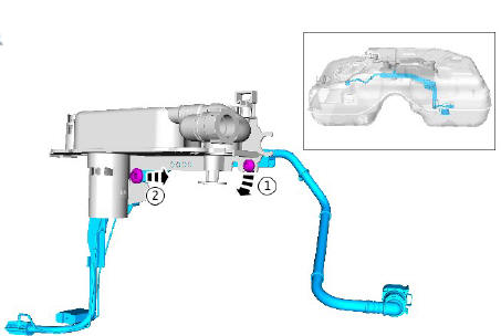
Before disconnecting or removing the components, make sure the area around the joint faces and connections are clean.
NOTES:
- Some variation in the illustrations may occur, but the essential information is always correct.
- Some components shown removed for clarity.
- Removal steps in this procedure may contain installation details.
Disconnect the battery ground cable.
Refer to: Specifications (414-01 Battery, Mounting and Cables, Specifications).
Refer to: Engine Cover - INGENIUM I4 2.0L Diesel (501-05 Interior Trim and Ornamentation, Removal and Installation).
CAUTION:
Be prepared to collect escaping coolant.
.jpg)
WARNING:
Be prepared to collect escaping fuel.
.jpg)
.jpg)
INSTALLATION
- To install, reverse the removal procedure.
- Refer to: Fuel System Bleeding - INGENIUM I4 2.0L Diesel (310-00 Fuel System - General Information, General Procedures).
Fuel Tank and Lines - Ingenium i4 2.0l Diesel Fuel Level Sensor (G1779690)
Removal
WARNINGS:
- Fuel may still be present in the fuel tank after draining.
- Place the vehicle in a well ventilated, quarantined area and arrange ' No Smoking/Petrol Fumes' signs about the vehicle.
- Do not carry or operate cellular phones when working on or near any fuel related components. Highly flammable vapors are always present and may ignite. Failure to follow these instructions may result in personal injury.
- The spilling of fuel is unavoidable during this operation. Ensure that all necessary precautions are taken to prevent fire and explosion.
- Be prepared to collect escaping fuel.
CAUTION:
Before disconnecting or removing components, ensure the area around the joint faces and connections are clean. Plug open connections to prevent contamination.
NOTES:
- Some variation in the illustrations may occur, but the essential information is always correct.
- Some components shown removed for clarity.
- Removal steps in this procedure may contain installation details.
Refer to: Fuel Pump and Sender Unit (310-01A, Removal and Installation).
Refer to: Fuel Pump and Sender Unit (310-01B, Removal and Installation).
.jpg)
WARNING:
Be prepared to collect escaping fuel.
.jpg)
INSTALLATION
- To install, reverse the removal procedure.
READ NEXT:
 Fuel Tank and Lines - Ingenium i4 2.0l Diesel Fuel Pump and Sensor Unit
(G1779691)
Fuel Tank and Lines - Ingenium i4 2.0l Diesel Fuel Pump and Sensor Unit
(G1779691)
SPECIAL TOOL(S)
REMOVAL
WARNINGS:
After carrying out repairs, the fuel system must be checked
visually
for leaks. Failure to follow this instruction may result in personal
injury.
This proced
Fuel Tank and Lines - Ingenium i4 2.0l Diesel Fuel Tank (G1779692) / Removal
and Installation
GENERAL EQUIPMENT
Transmission jack
REMOVAL
WARNINGS:
Fuel may still be present in the fuel tank after draining.
Place the vehicle in a well ventilated, quarantined area and
arrange
' No Smoking
Fuel Tank and Lines - Ingenium i4 2.0l Diesel / Description and Operation
COMPONENT LOCATION - SHEET 1 OF 2
Fuel filler pipe connection
Fuel pump module
Fuel tank breather pipe
Vent tube
Support bracket
Fuel level sensor - 'B'
Fuel level sensor - 'A'
Line - fuel s
SEE MORE:
Engine Cooling - Ingenium i4 2.0l Diesel / Diagnosis and Testing
PRINCIPLES OF OPERATION
For a detailed description of the Engine Cooling system, refer to the
relevant Description and Operation section in the workshop manual.
REFER to: Engine Cooling (303-03B Engine Cooling - INGENIUM I4 2.0L
Diesel, Description and Operation).
INSPECTION AND VERIFICATION
WARNIN
Wheels and Tires - Tire
Pressure Monitoring
System Receiver (G1780281)
/ Removal and Installation
REMOVAL
NOTES:
Some variation in the illustrations may occur, but the essential
information is always correct.
Some components shown removed for clarity.
Removal steps in this procedure may contain installation details
Refer to: Overhead Console (501-12 Instrument Panel and Console,
Removal
