Land Rover Discovery: Electric Throttle
.jpg)
The electric throttle is located between the charge cooler connecting pipe and the intake manifold. The electric throttle is secured to the manifold with four Torx head bolts.
The electric throttle comprises the throttle body, a round throttle butterfly valve which is actuated by a motor and a Throttle Position (TP) sensor. The electric throttle is controlled by the ECM which receives positional signals from the TP sensor.
If a failure of the motor occurs, the butterfly valve is returned to an emergency position by springs. The butterfly valve remains partially open with limited engine speed available to the driver.
The electric throttle has 5 wires which are connected to the ECM. Two wires supply 12V current and ground for the Direct Current (DC) motor. Three wires are connected to the TP sensor. One wire supplies a 5V reference voltage to an analogue, Hall-Effect sensor. Two further wires provide the TP sensor negative and positive signal feedback to the ECM. As the throttle angle increases, the output of the negative sensor decreases and the output of the positive sensor increases.
The motor is a Direct Current (DC) stepper motor which drives a gear wheel and two springs; one for opening and one for closing. The motor rotates the spindle to which the butterfly valve is attached. PWM signals from the ECM control the motor to adjust the position of the butterfly valve, regulating the amount of air entering the inlet manifold for combustion. Movement of the motor is achieved by changing the polarity of the power supply to the DC motor, allowing it to be operated in both directions. The butterfly valve and the DC motor has two maximum positions; butterfly valve closed which allows minimal air flow through the electric throttle into the intake manifold and butterfly valve open which allows maximum air flow into the intake manifold.
The ECM calculates the butterfly valve position by comparing the feedback signal from the TP sensor to a stored value at a known datum position. The ECM performs a self-test and a calibration routine on the butterfly valve position at each ignition cycle. This is achieved by the ECM powering the DC stepper motor to fully close the butterfly valve and, if required, fully open the butterfly valve.
The ECM monitors the DC stepper motor and the TP sensor for faults and can store fault related Diagnostic Trouble Codes (DTC). The codes can be retrieved using an approved diagnostic system. In the event of a fault the engine Malfunction Indicator Lamp (MIL) in the IC will also be illuminated.
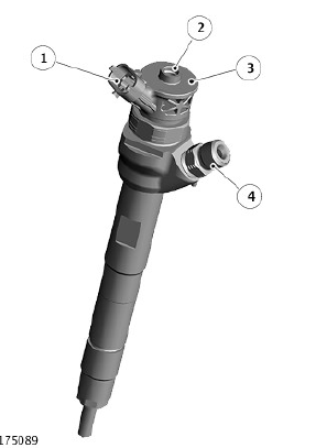
FUEL INJECTORS

- Electrical connector
- Low Pressure (LP) fuel leak-off connection to the fuel filter
- Data matrix and injector information
- High Pressure (HP) fuel supply connection from the fuel rail
Four fuel injectors are located through a hole in the camshaft carrier. Each injector is sealed by a seat in the cylinder head and held in position by a clamp which is secured to the camshaft carrier with a bolt which passes through the carrier into the cylinder head.
Each injector is supplied with pressurized fuel from the fuel rail and delivers finely atomized fuel directly into the combustion chambers. Each injector is individually controlled by the ECM which operates each injector in the firing order and controls the injector opening period via PWM signals. Each injector receives a 12V supply from the ECM and, using programmed injection/timing maps and sensor signals, determines the precise pilot and main injector timing for each cylinder. If battery voltage falls to between 6 and 9V, fuel injector operation is restricted, affecting emissions, engine speed range and idle speed.
The ECM can monitor the injector operation by monitoring both connections to the injector. Each injector can be diagnosed by the ECM and DTCs stored. The codes can be retrieved using an approved diagnostic system.
If a fuel injector fails, the engine will suffer from unstable idle speed, poor Noise, Vibration and Harshness (NVH) and poor emissions performance. The engine Malfunction Indicator Lamp (MIL) in the IC will also be illuminated.
In the event of a failure of a fuel injector, the following symptoms may be observed:
- Engine misfire
- Idle irregular
- Reduced engine performance
- Reduced fuel economy
- Difficult starting
- Increased smoke emissions.

